This is the seventh part in an ongoing series of articles examining the changes found in the UEFI 2.4 specification. This time we look at the expansion of the low-level network interfaces to support more than 256 network identifiers. This is not about maintaining more than 256 connections in a UEFI environment, but rather tracking them and uniquely identifying them so that, for example, their firmware can be updated.
Specifically, this updates the EFI_NETWORK_INTERFACE_IDENTIFIER_PROTOCOL, updating its revision and changing the last UINT8 field to a UINT16. This change allows the new protocol to be created even for existing systems, since they will have a interface number of 0-255 and, since UEFI is little-endian, the low 8 bits of a UINT16 have the lowest address in a structure.
This update also modifies the UNDI structures, which are used by standard network cards to expose their networking capabilities. In previous revisions, there were two reserved bytes at offsets 0x0A and 0x0B, which were always set to 0. Now, one of these reserved bytes is take as the upper 8 bits of the interface count field. The lower 8 bits are still found at offset 0x03.
Now most of us don't normally deal with systems that hundreds of network interfaces. But then again, most of us aren't Facebook or Google where there are thousands of little boxes in a building somewhere and all of them need to be hooked up, configured and brought on-line. The earliest phase of the configuration is called bare-metal provisioning, where a new box, fresh out of the box is just plugged into a network and boots over that network into an environment that updates its settings and installs the OS that it will use. UNDI helps handle that in UEFI, by providing a standardized low-level interface to the NICs, but it was designed long before this number of interfaces was even considered remotely possible.
But now the UEFI specification can handle it.
Saturday, August 31, 2013
Thursday, August 29, 2013
UEFI 2.4 Review, Part 6: HII Forms op-code for displaying a warning message
This is the sixth article in a series reviewing the changes in the UEFI 2.4 specification. This time, we look at a topic near and dear to my heart: a new IFR opcode, EFI_IFR_WARNING_IF_OP. For those of you who have followed this blog, you know I've spent a lot of time assembling and disassembling the opcodes of the Internal Forms Representation (IFR) with my tools. Part of that is because I spent a lot of time as a part of the UEFI Configuration Sub-Team trying to work out how to make a specification that was powerful enough to do what was needed, small enough to actually fit in a flash device, and flexible enough to allow alternative implementations from a 1-line DVD player to a full-blown GUI interface.
UEFI encodes the configuration settings information in a byte-code called IFR. IFR consists of a stream of binary-encoded opcodes. Opcodes can be nested inside each other. So drivers can produce form packages which contain zero or more form sets, each of which contains zero or more forms (pages), each of which contains zero or more statements (static items) or questions (items with an associated value). Questions contain a lot of information about their value's data type as well as expressions that perform range checking. Starting in the UEFI 2.1 specification, there were two IFR opcodes that allowed for question value error checking. The EFI_IFR_INCONSISTENT_OP checked the value immediately after it was changed by the user. The EFI_IFR_NO_SUBMIT_OP checked the value before the form containing the question was closed. Both of these also provide for an error message that will be presented to the user.
Now, with the UEFI 2.4 specification, there is a third: EFI_IFR_WARNING_IF_OP. Like the other two, this opcode has an expression that is evaluated and a message to present to the user. The expression is evaluated when the user attempts to leave the question or leave the form. But rather than an error condition, where the user cannot proceed without correcting something, this merely presents a warning to the user which the user must either acknowledge before leaving the form or which can optionally timeout.
This opcode presents additional concerns about a proposed change on the part of the user. For example, if the user disabled security settings or was about to do something which would cause loss of data. Without this opcode, driver writers often resorted to popping up messages in the Callback() member of their EFI_CONFIG_ACCESS_PROTOCOL. but without actually knowing the type of display being used (as well as the style and color palette of the setup utility) this was risky or garish.
On older browser implementations, this opcode will be ignored.
This update to UEFI 2.4 gives the driver better control over the user experience when they want to change certain configuration settings.
Wednesday, August 28, 2013
UEFI 2.4 Review, Part 5: EFI_DISK_IO2_PROTOCOL to support asynchronous I/O
This is the fifth part of an on-going series of articles examining the changes in the UEFI 2.4 specification. This week we are examining a brand new protocol, the EFI_DISK_IO2_PROTOCOL. As the "2" indicates, this is an enhanced version of a protocol that existed previously. In this case, the EFI_DISK_IO_PROTOCOL has existed for a long time, at least back to the EFI days. These protocols both give byte oriented access to the contents of a physical or virtual device.
The EFI_DISK_IO_PROTOCOL was typically layered on top of the EFI_BLOCK_IO_PROTOCOL. The UEFI 2.3.1 specification added the EFI_BLOCK_IO2_PROTOCOL. This provided asynchronous access to storage devices at the block level, so that processing could continue while the blocks were being read or written.
But the same specification never updated the EFI_DISK_IO_PROTOCOL. Since EFI_DISK_IO_PROTOCOL was still synchronous (requiring all reads or writes to continue before returning) and all of the file system related protocols use it, they could not take advantage of the performance gains offered. This was because the ReadDisk() and WriteDisk() functions were defined to wait for all reads or writes to complete before returning. So even if they used EFI_BLOCK_IO2_PROTOCOL, they couldn't return any sooner.
Now, with the new EFI_DISK_IO2_PROTOCOL protocol and related updates to the EFI_FILE_PROTOCOL protocol, the file system drivers (such as those for FAT32 or El Torito or even EXT2/3/4) can offer enhanced performance by allowing processing to continue while disk operations complete.
We will look at the enhancements to the EFI_FILE_PROTOCOL in more detail in a later article.
UEFI 2.4 offers enhanced storage performance, which can greatly speed up boot time and other disk-bound activities.
Tuesday, August 27, 2013
UEFI 2.4 Review, Part 4: Require network drivers to return EFI_NO_MEDIA
This is the fourth in a series of articles reviewing the individual changes in the UEFI 2.4 specification. This time, we're looking at the requirement that the EFI_NO_MEDIA error be returned from a wide variety of network related protocols. Typically, EFI_NO_MEDIA indicates that there is no storage media (for disk-related functions) or no cable (for network related functions).
This update requires the low-level networking drivers to produce this error on their implementations of the Transmit() and Receive() functions in the Managed Network Protocol (MNP) and then each of the networking standard drivers that consume this protocol will propagate this error upwards to their callers. So, for example, the IP4/IP6, UDP4/UDP6, TCP4/TCP6 protocols have Transmit() and Receive(), the DHCP4/DHCP6 protocols have Start() and Stop() functions and the MTFTP4/MTFTP6 protocols have ReadFile() and WriteFile(). All of them now can report EFI_NO_MEDIA.
Why? So that calling applications can quickly determine if the cable is removed and decide to take appropriate action. Previously, there was no status code which clearly described this scenario, leaving the caller to try and decide if some sort of timeout had occurred due to a routing issue, or due to the cable not being present. Now the callers can make an intelligent choice.
Strangely, the SIMPLE_NETWORK protocol was not updated, although it is called out in the notes. My feeling is that this was either (a) a mistake or (b) a determination that some existing drivers couldn't handle the updated language.
UEFI is becoming a more capable networking platform all the time. Don't be surprised if higher level networking standards make their appearance soon. Then we'll wonder why we ever booted ;-)
Monday, August 26, 2013
UEFI 2.4 Review, Part 3: Forbid creation of non-spec variables in EFI_GLOBAL_VARIABLE namespace
This is the third part in a series looking in detail at the updated features of the UEFI 2.4 specification. This week we look at a new restrictions placed on UEFI variables. UEFI variables services provide a system-wide repository for data, either volatile (that is, they are lost at power-off or reset) or non-volatile (that is, they are saved across a power-off or reset).
Each UEFI variable has a name composed from two parts: a VendorGuid and a VariableName. The two-part scheme allows different vendors (e.g. OEMs, silicon, software or BIOS vendors) to create their own variables without fear of conflicting with a name already chosen by someone else. The main way to avoid this is conflict is for each vendor to choose their own GUID.
The UEFI specification (chapter 3) defines some variables and most of them use the GUID EFI_GLOBAL_VARIABLE. What had happened, historically, is that some 3rd parties and BIOS vendors started to use this GUID for their own variables. This defeats one of the key design objectives of the UEFI variable names.
So, with UEFI 2.4, the specification now says that "Implementations must only permit the creation of variables with a UEFI Specification-defined VendorGuid when these variables are documented in the UEFI Specification." (section 3.2) This will cause an error to be returned
While EFI_GLOBAL_VARIABLE is the most common VendorGuid in the UEFI Specification, it is not the only one. There is the EFI_HARDWARE_ERROR_VARIABLE GUID (for hardware error records, section 7.2.3) and EFI_IMAGE_SECURITY_DATABASE GUID (for the secure boot related variables, section 27.5.3).
By adding this restriction, the UEFI-defined variable names will not conflict with vendor-specific variable names in the future. I think that similar rules will be followed for the EFI_ prefix for symbol names. There have been a lot of implementations, include tianocore.org, that use EFI_ for their own purposes. In the PI specification, this led to problems when the names that the UEFI specification wanted had already been used by a popular implementation. This proactive step by UEFI 2.4 prevents this issue for UEFI variables.
Sunday, August 25, 2013
UEFI 2.4 Review, Part 2: VendorKeys UEFI Variable
Is the system secure? That's a critical question for the IT department. When UEFI added the secure boot capabilities and Microsoft started using them, it raised quite a stir. It quickly raised the question: who can say who can boot. Well, for most platforms, OEMs (and their BIOS vendors) provide the means for users to change the secure boot policy using the firmware's built-in configuration utility.
That raises another question: did the users do anything? Did they change the secure boot policy? Now that's something my IT department would be interested in. With this new UEFI variable VendorKeys, a simple utility could verify whether something related to secure boot had been verified. If it is 0, it has been modified. If it is 1, it is unmodified.
This variable is not stored in the platform's non-volatile storage, like flash. This may seem insignificant. But variables written by OS applications must be placed in non-volatile storage. If it is not in non-volatile storage, it must have been written by the firmware. That means it cannot be easily spoofed. If it could be spoofed, then an attacker could make it look like nothing had changed. If the attacker could do that, it could prevent an IT application from looking deeper.
Keeping the system secure, and proving it, the UEFI way.
Saturday, August 24, 2013
UEFI 2.4 Review, Part 1: ResetSystem() Update
This series goes through the significant updates found in the UEFI 2.4 specification. Starting off minor, we look at the updates to the ResetSystem() runtime service. Previously, there were three types: EfiResetCold, EfiResetWarm, and EfiResetShutdown. So what other types of reset do you need?
Well, there are resets and resets. In many platforms, there are actually many devices that can start a reset. The CPU itself can be reset. Or, the I/O controller can be reset, that resets the PCI bus and the CPU. Or, in some systems, an embedded controller can be reset, that resets the I/O controller, that resets the PCI bus and the CPU.
Now resets have all sorts of interesting side effects. Among them is the tendency to unlock all sorts of storage or locked configuration registers. In particular, some embedded controllers do not permit their internal flash to be updated unless they themselves are reset. But that kind of reset does not normally happen with either EfiResetWarm or EfiResetCold. Hmm...what to do?
Well, the UEFI 2.4 specification added a new reset type: EfiResetPlatformSpecific. This reset type can be further qualified by a GUID appended to the end of the ResetData after the null-terminated string.
There was nothing after the string in previous specifications. It is always a system-wide reset and, if the GUID is not recognized by the platform firmware, then it can choose the type of reset. But if the GUID is recognized, it can perform a platform-specific type of reset. For example, it could reset the embedded controller so that its on-chip flash would be unlocked and updated.
Useful, so that platform vendors don't need to use their own undocumented services or parameter values.
Next time: out-of-band key modification.
Friday, August 23, 2013
Automatic Build Programs - Part 2
In the last post, we discussed the program AutoBuild.bat, which downloads the latest revision of EDK2, builds the EDK2 environment, and if EDK2 does not build, AutoBuild.bat emails an error message to a specified address. This article will discuss how to set up AutoBuild.bat to run on a daily schedule.
To set up AutoBuild.bat, follow the instructions in Part 1.
SenderEmail is the email address that the error message will be sent from. SenderPassword is the password for the sending email address. RecieverEmail is the email that will receive the error message. SMTPServer is the SMTP server address for the sending email address. These inputs are discussed further in Part 1.
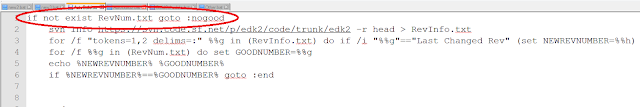 Now that AutoBuild.bat can build the latest revisions of EDK2 on a daily basis, we need to make sure that AutoBuild.bat only builds EDK2 if it finds a revision of EDK2 that it has not built before. To check if it has built a certain revision, AutoBuild.bat searches to see if RevNum.txt exists. RevNum.txt contains the revision number for the last revision to be built. If RevNum.txt does not exist, AutoBuild.bat has not built a revision before, so AutoBuild.bat immediately starts downloading and building the latest revision. If RevNum.txt does exist, it signifies that a previous revision has been built.
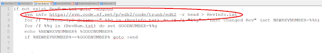 AutoBuild.bat uses svn info in order to get the revision number of the latest revision of EDK2 uploaded to Subversion.
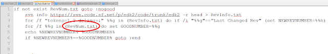
AutoBuild.bat also uses RevNum.txt to get the revision number of the last EDK2 revision built by AutoBuild.bat.
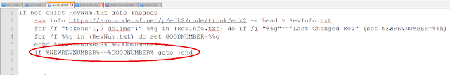
AutoBuild.bat then checks to see if the revision number in RevNum.txt is equal to the revision number of the latest revision. If they are the same, AutoBuild.bat doesn't build the revision because it already has built it. Otherwise, AutoBuild.bat downloads the new revision of EDK2.
To set up AutoBuild.bat, follow the instructions in Part 1.
Schtasks
To schedule AutoBuild.bat, you will need to call SCHTASKS in the Command Prompt. To set up AutoBuild.bat's schedule correctly, use the following structure:
schtasks /create /sc daily /tn taskname /st HH:MM /tr "c:\sourcecode\AutoBuild SenderEmail SenderPassword RecieverEmail SMTPServer"
In the line above, taskname is the name assigned to the schedule. HH:MM is the time when AutoBuild.bat will run. Schtasks uses 24-hour time, so 11:00am should be written as 11:00 and 11:00pm should be written as 22:00.
If any of the arguments passed into the /tr section of schtasks have spaces, use the following structure when writing the /tr section:
/tr "\"c:\sourcecode\AutoBuild\" \"argument1 with spaces\" argument2"
The schedule frequency, or /sc, is currently set to daily. If you want to change the frequency, all other valid /sc inputs can be found here.
The following line shows an actual example of using schtasks:
schtasks /create /SC daily /TN BuildSchedule /ST 11:00 /TR "c:\sourcecode\AutoBuild2 sender@email.com MyPassword1 reciever@email.com smtp.email.com"
The following line shows an actual example of using schtasks:
schtasks /create /SC daily /TN BuildSchedule /ST 11:00 /TR "c:\sourcecode\AutoBuild2 sender@email.com MyPassword1 reciever@email.com smtp.email.com"
Checking Conditions
 Now that AutoBuild.bat can build the latest revisions of EDK2 on a daily basis, we need to make sure that AutoBuild.bat only builds EDK2 if it finds a revision of EDK2 that it has not built before. To check if it has built a certain revision, AutoBuild.bat searches to see if RevNum.txt exists. RevNum.txt contains the revision number for the last revision to be built. If RevNum.txt does not exist, AutoBuild.bat has not built a revision before, so AutoBuild.bat immediately starts downloading and building the latest revision. If RevNum.txt does exist, it signifies that a previous revision has been built.
 AutoBuild.bat uses svn info in order to get the revision number of the latest revision of EDK2 uploaded to Subversion.

After checking for new revisions, AutoBuild.bat runs as described in Part 1. Using schtasks for EDK2, you can create a schedule for AutoBuild.bat and send error messages to the people who created the bad revisions of EDK2. This can help to more efficiently monitor and manage revisions of EDK2.
Tuesday, August 20, 2013
Automatic Build Programs - Part 1
Because EDK2 is opensource, people around the world are constantly updating its code. Managing EDK2's thousands of revisions can be difficult. This article discusses the program AutoBuild.bat, which helps to simplify the revision management process for EDK2.
AutoBuild.bat has three major steps. First, the program downloads the latest version of EDK2 from Subversion. After that, AutoBuild.bat builds the EDK2 environment. The third function is to email an error message if the EDK2 environment could not build. The email will also attach enough information for the receiver to begin fixing the bug.
This article assumes that the folder c:\sourcecode exists.
 After Blat has been downloaded, open the folder containing Blat's contents and select the folder "blat311".

Within the "blat311" folder, open the folder "full." Select blat.exe and copy it by pressing Ctrl+C.

Go to the folder c:\sourcecode and paste blat.exe by pressing Ctrl+V. This will allow AutoBuild.bat to use Blat while running. This article discusses the configuration of blat later on.
 After SysLib is downloaded, you can find AutoBuild.bat inside the folder "Tools" within SysLib. In order to run, AutoBuild.bat must be moved out of this folder into c:\sourcecode because all contents of c:\sourcecode\edk2 are deleted when AutoBuild.bat is run, and if it is not moved, AutoBuild.bat will delete itself from c:\sourcecode\edk2 as well.

If you decide that you want to change the directory for EDK2 to be download to, open AutoBuild.bat, and replace every instance of c:\sourcecode\edk2 with the desired directory.
 If you downloaded Blat to a folder other than c:\sourcecode, open AutoBuild.bat, and replace every instance of c:\sourcecode with the desired directory. Remember to copy blat.exe and AutoBuild.bat into the new directory.
NOTE: If you want to change both the EDK2 download directory and the Blat directory, change the EDK2 download directory first.
 If the SMTP Server Address does not use the standard port number, open AutoBuild.bat. Near the bottom of the file, on the line starting with "blat", the word -port is written followed by a number. This number is the port number that Blat uses to connect to the email server so it can send an email. Replace the written port number with the port number for the SMTP server that will be sending the email, then save AutoBuild.bat.


Before building, AutoBuild.bat sets the work space and build environment for EDK2. The program sets the work space to c:\sourcecode\edk2, and initializes the build environment by calling edksetup.bat.

After setting up the build environment, AutoBuild begins to build EDK2. All build information is sent to the file BuildLog.txt.

While building, the build process sets the variable %ERRORLEVEL%. If %ERRORLEVEL% equals zero, no errors occurred during the build, otherwise, there was an error during the build process. AutoBuild uses the %ERRORLEVEL% to determine whether a build was successful or not.

If the build was successful, AutoBuild uses svn info to retrieve the information on the revision that was just built and save it in the text file BuildInfo.txt. AutoBuild.bat searches through BuildInfo.txt until it finds revision number. The information on that revision is then appended to BuildLog.txt. The revision number is then saved into the file GoodRevision.txt.

If the build produces an error, AutoBuild uses svn info to get the information on the revision. The program saves the revision number into OtherInfo.txt. AutoBuild then tests to see if the file GoodRevision.txt exists. If GoodRevision.txt does exist, the program uses svn log to get the information on each revision since the last successful build. The program appends the information to BuildLog.txt. If GoodRevision.txt doesn't exist, the current revision is set as GoodRevision.txt. The revision's information is still appended to build log, but the statement "No previous successfully build revision could be found." is also appended to BuildLog.txt.
 After the information has all been appended to BuildLog.txt, Blat is called to send an email to the specified email address. BuildLog.txt is attached to this email as well.
AutoBuild.bat has three major steps. First, the program downloads the latest version of EDK2 from Subversion. After that, AutoBuild.bat builds the EDK2 environment. The third function is to email an error message if the EDK2 environment could not build. The email will also attach enough information for the receiver to begin fixing the bug.
This article assumes that the folder c:\sourcecode exists.
Blat
AutoBuild.bat emails an message to a specific address after EDK2 has been parsed. To send this email, AutoBuild.bat uses the program Blat. Blat must be download from blat.net before AutoBuild.bat can be run.
 After Blat has been downloaded, open the folder containing Blat's contents and select the folder "blat311".
Within the "blat311" folder, open the folder "full." Select blat.exe and copy it by pressing Ctrl+C.

Go to the folder c:\sourcecode and paste blat.exe by pressing Ctrl+V. This will allow AutoBuild.bat to use Blat while running. This article discusses the configuration of blat later on.
AutoBuild.bat
To get AutoBuild.bat, download SysLib using Subversion from the following link: https://svn.code.sf.net/p/syslibforuefi/code/trunk
 After SysLib is downloaded, you can find AutoBuild.bat inside the folder "Tools" within SysLib. In order to run, AutoBuild.bat must be moved out of this folder into c:\sourcecode because all contents of c:\sourcecode\edk2 are deleted when AutoBuild.bat is run, and if it is not moved, AutoBuild.bat will delete itself from c:\sourcecode\edk2 as well.
If you decide that you want to change the directory for EDK2 to be download to, open AutoBuild.bat, and replace every instance of c:\sourcecode\edk2 with the desired directory.

NOTE: If you want to change both the EDK2 download directory and the Blat directory, change the EDK2 download directory first.
Using AutoBuild.bat
AutoBuild.bat is called from the Command Prompt using the following structure:
AutoBuild SenderEmail SenderPassword RecieverEmail SMTPServer
AutoBuild SenderEmail SenderPassword RecieverEmail SMTPServer
In the above line, SenderEmail is the email address that the error message will be sent from. SenderPassword is the password for the sending email address. RecieverEmail is the email that will receive the error message. SMTPServer is the SMTP server address for the sending email address.
 If the SMTP Server Address does not use the standard port number, open AutoBuild.bat. Near the bottom of the file, on the line starting with "blat", the word -port is written followed by a number. This number is the port number that Blat uses to connect to the email server so it can send an email. Replace the written port number with the port number for the SMTP server that will be sending the email, then save AutoBuild.bat.
 The AutoBuild Process

AutoBuild.bat begins by deleting the folder c:\sourcecode\edk2, and all its contents, if it exists. AutoBuild then recreates c:\sourcecode\edk2. The program calls svn checkout, which repopulates c:\sourcecode\edk2 with the latest revision of EDK2 found at https://svn.code.sf.net/p/edk2/code/trunk/edk2.


While building, the build process sets the variable %ERRORLEVEL%. If %ERRORLEVEL% equals zero, no errors occurred during the build, otherwise, there was an error during the build process. AutoBuild uses the %ERRORLEVEL% to determine whether a build was successful or not.


If the build produces an error, AutoBuild uses svn info to get the information on the revision. The program saves the revision number into OtherInfo.txt. AutoBuild then tests to see if the file GoodRevision.txt exists. If GoodRevision.txt does exist, the program uses svn log to get the information on each revision since the last successful build. The program appends the information to BuildLog.txt. If GoodRevision.txt doesn't exist, the current revision is set as GoodRevision.txt. The revision's information is still appended to build log, but the statement "No previous successfully build revision could be found." is also appended to BuildLog.txt.
 After the information has all been appended to BuildLog.txt, Blat is called to send an email to the specified email address. BuildLog.txt is attached to this email as well.
This post sets up the basic ideas and principles behind an automatic build program. A later post will discuss how to create a schedule for AutoBuild.bat.
Thursday, August 15, 2013
Composite Images and Transparency
 In this project, I endeavored to create a visual thermometer, which would change the displayed temperature based on user input. I did not want to have to store a dozen different sprites to be able to display different temperatures, however, because the images would be so similar, the only difference being the length of the red bar inside the thermometer. To do this, I tried out a few different things. First was the display of a smaller chunk of a larger image, so that rather than keeping track of many images of different thermometers, I could just display bigger or smaller sections of a single image. Second is the composition of different images on top of one another to create one image. Finally, I implemented transparency for the purpose of combining multiple images.
 This article assumes you have read the previous article on displaying images in a cycle using sprites.
The code for this project can be found on sourceforge, here.
Because the only part of the thermometer that changes is the height of the red bar, and it is a very simple image, I figured I didn't need to save all the different sprites, and could just use one image of a red bar to display all the different heights. Basically, what I decided to do was to store a single image of the largest the bar could be and display smaller sections of the image, depending on user input. Rather than displaying the entire image, only a small section at a time is displayed.
 Like with sprites, I created a loop that waited for user input of either an UP or DOWN keystroke, and would call another function from there. However, instead of changing the pointer to the image, it increases or decreases the height of the displayed image. This way, the actual image that is used stays the same, but a shorter or taller section is displayed.
Next is the combination of several images to make one single image that will be displayed. Since only the red bar in the thermometer would be changing, I figured I could just stack the different parts on top of each other: the white background, the red bar, and the tick marks.
Rather than calling Blt() several different times for each of the different layers, I merged the three layers into one bitmap and then called Blt() once to display that combined image.
First, I started by creating a buffer of type EFI_GRAPHICS_OUTPUT_BLT_PIXEL, set to be the size of the largest bitmap I would be displaying (the background). I then filled each entry with a black pixel (each color set to 0).
I then copied each layer into the new buffer, starting with the background. The copy function takes the information from the destination and the source buffers, including their heights and widths, as well as the X and Y coordinates to which the source buffer should be copied. The function will locate the pixel specified, and copy the source buffer into the destination buffer, clipping the edges of the source buffer if they extend past the edges of the destination buffer.
Transparency is also implemented in this function. I wanted to put the tick marks on the thermometer, but couldn't do it with simple image merging because .BMP files (the only supported image file at the moment) do not have transparency. So in this function, while merging all the image buffers together, pure black (the values for red, blue and green are all 0) is interpreted as transparent, and it does not copy the source pixel to the destination buffer.

These are the three layers used for the thermometer image. I wanted black tick marks on the thermometer, but since black is interpreted as transparent, I instead used a very dark blue to draw the marks, and then colored the rest of the image black.


I did try to use the DrawImage() function for EFI_HII_IMAGE_PROTOCOL in the open source tianocore.org implementation because the spec describes the ability for it to implement transparency. However, transparency had not been fully implemented in that function, so I decided not to use it at all and implement it all manually.
For my next project, I plan on using this thermometer in a simple puzzle-based game.
Wednesday, August 07, 2013
Writing an IFR Assembler for UEFI - Part 4
This is part 4 of Writing an IFR Assembler for UEFI.
To set up the IFR Assembler, follow the instructions in Part 1.
To learn about the higher-level parsing process of the IFR Assembler, view Part 2.
To learn about the token-parsing process of the IFR Assembler, view Part 3.
This post will walk you through the expression-parsing process of the IFR Assembler.
In any mathematical equation, there is an order of precedence. Order of precedence is the order in which the different operators in an equation are executed. This is why multiplication is done before addition in every equation. Expressions in C, like mathematic equations, have their own order of precedence to organize the order in which the operators are processed.
To see the complete order of precedence for the C programming language, click here.
 Part 2 of this series discussed ParseOperand(), which calls a different parsing function depending on what type of operand is found.
 If an expression is found, ParseExprOperand() is called, and ParseExprOperand() calls ParseExpr().
 ParseExpr() is the beginning of a large recursive loop. Before anything is even parsed, ParseExpr()
calls ParseExpr2(), and ParseExpr2() calls ParseExpr3(), and this process goes on until ParseExpr12().
 The functions ParseExpr() through ParseExpr12() determine the order of precedence for the expression parsing. ParseExpr12() hold the operands and operators with the highest precedence, and ParseExpr() holds those with the lowest. These functions tell the parser what to do with the each operator and operand and what type of token to expect next. See table 4.1 for a full list of operands and operators parsed by each function.


When operators within an expression are parsed, they are turned into their own sub-expression. Depending on the number of operands that the operator requires, a different function is called. For example, if the operator has only one operand, like ++ (T_P__PLUS_PLUS), it is parsed with the function CreateExprUnary().
 On the other hand, if the operator is like + (T_P__PLUS), which has two operands, the function CreateExprBinary() is called.
 If the parser finds a question mark (T_P__QUESTION), that means that there is a conditional statement involved (EXPR_O_CONDITIONAL). Conditional statements are the only trinary expressions, which requires three operands, so if a question mark is found, CreateExprTrinary() is called. These functions create expressions for the operators and expect a specific number of operands.

If the operands in the expression are unsigned integers (T_P_UINT), CreateExprUint() is called. This function creates an expression from that integer.

If the operand is either true (T_P_TRUE) or false (T_P_FALSE), the function CreateExprBoolean() is called to make the expression with a Boolean response.

If the operand found turns out to be an IFR opcode, it is treated like a function and function parameters are added to the operand. These operands are found within the parentheses of the opcode and are not written as a separate expression. Instead, their information is recorded as operands of the opcode's expression. A different function is called depending on the number of operands the opcode can hold. If the opcode has a set number of operands, then CreateFn() is called.
 If the number of operands within an opcode is variable, then CreateVarFn() is called. In each of these function, all the operands of the opcode are written into the expression with the opcode itself.
 If found within an expression, a left parenthesis (T_P_LPAREN) represents the beginning of another expression nested within the first. For example, in the expression x * (y - z), the section y - z can stand alone as its own expression since it is inside parentheses. Because the expression within the parentheses is, in fact, a separate expression, ParseExpr() is called recursively to parse the nested expression until it finds the expression's end, which is marked by a right parenthesis (T_P_RPAREN). After being parsed, the entire nested expression is returned and is treated as a single operand. In our example, the (y - z) would be treated as a single operand, w, so that the equation would read x * w.
 Once the parser begins going through the expression, it begins to organizes the operands and operators by order of precedence. The way they are organized can be described as a type of expression tree. The higher the precedence of a specific token, the closer it will be to the leaves of the expression tree. Inversely, the lower the precedence of a token, the closer the token will be to the roots of the tree. In the expression a * b + c + d, the expression-parser would begin parsing the expression. First, the parser would point to a. Since a is an operand and operands receive the highest precedence, a will be set as a leaf in the tree.

The parser would then point to the asterisk, which serves as the multiplication operator. Since the asterisk is an operator, it has a lower precedence than a, so the multiplication operator is moved up a level. The multiplication operator requires two operands, each one represented by a branch coming off of it in the tree. a is set to one of operands of the multiplication operator.

When b is reached, the parser sees that the multiplication operator still has another required operand, so b is set as that operand.

The parser then moves to the first plus sign, which is the addition operator. Since it is not an operand, the plus sign is moved up a level. Since the plus sign has less precedence than the asterisk, it is moved a level higher than the asterisk. The asterisk is set as one of the operands of the plus sign. The next token, c, is set as the other operand for the plus sign.

The parser moves on to the second plus sign. Since the plus sign has less precedence then an operand, the plus sign moves up a level from c. Though both plus signs are on the same level of precedence, precedence goes left to right for plus signs, so the first plus sign takes precedence. The second plus moves a level higher than the first plus sign, becoming the root of the expression tree. The parser then moves onto d, which becomes the second operand of the second plus sign.
 All expression are put within an opcode, usually a conditional. When an expression is finished being parsed, it is returned to ParseForm(), which writes the opcode's information into the output buffer. In order to write the opcode's expression to the output buffer, the function WriteExpr() is called.

WriteExpr() calls WriteExprHelper(), which then takes the expression and creates an opcode out of the expression and its operands. After creating the opcode, the opcode is returned to WriteExpr(), which writes the opcode to the output buffer.
Normally, operands are written to the buffer before the operator is written, so if a + b is found, the opcode, a b + would be written to the output buffer. If an expression does has a specific order for its operators and operands to be written in, an expression-specific function is called. See Table 4.2 to view these expression-specific functions.

This finishes our series on Writing the IFR Assembler for UEFI. The IFR Assembler used does not several situation. The IFR Assembler does not handle any packages other than form packages nor does it have an optimization process. Also, the IFR Assembler is not free from bugs. This Assembler was simply made to as an example of how to set up an IFR Assembler for UEFI.
To set up the IFR Assembler, follow the instructions in Part 1.
To learn about the higher-level parsing process of the IFR Assembler, view Part 2.
To learn about the token-parsing process of the IFR Assembler, view Part 3.
This post will walk you through the expression-parsing process of the IFR Assembler.
Understanding Expression Hierarchy
Each expression is a series of operators and operands. Operators are actions that can be performed on values. These actions include addition and subtraction, multiplication and division, and comparisons along with many other actions. Operands are all of the values that the operators act upon.In any mathematical equation, there is an order of precedence. Order of precedence is the order in which the different operators in an equation are executed. This is why multiplication is done before addition in every equation. Expressions in C, like mathematic equations, have their own order of precedence to organize the order in which the operators are processed.
To see the complete order of precedence for the C programming language, click here.
The Expression-Parsing Process
 Part 2 of this series discussed ParseOperand(), which calls a different parsing function depending on what type of operand is found.
  If an expression is found, ParseExprOperand() is called, and ParseExprOperand() calls ParseExpr().
 ParseExpr() is the beginning of a large recursive loop. Before anything is even parsed, ParseExpr()
 calls ParseExpr2(), and ParseExpr2() calls ParseExpr3(), and this process goes on until ParseExpr12().
 The functions ParseExpr() through ParseExpr12() determine the order of precedence for the expression parsing. ParseExpr12() hold the operands and operators with the highest precedence, and ParseExpr() holds those with the lowest. These functions tell the parser what to do with the each operator and operand and what type of token to expect next. See table 4.1 for a full list of operands and operators parsed by each function.
Table 4.1 - Operands and Operators Parsed by Each Function


When operators within an expression are parsed, they are turned into their own sub-expression. Depending on the number of operands that the operator requires, a different function is called. For example, if the operator has only one operand, like ++ (T_P__PLUS_PLUS), it is parsed with the function CreateExprUnary().
 On the other hand, if the operator is like + (T_P__PLUS), which has two operands, the function CreateExprBinary() is called.
  If the parser finds a question mark (T_P__QUESTION), that means that there is a conditional statement involved (EXPR_O_CONDITIONAL). Conditional statements are the only trinary expressions, which requires three operands, so if a question mark is found, CreateExprTrinary() is called. These functions create expressions for the operators and expect a specific number of operands.
If the operands in the expression are unsigned integers (T_P_UINT), CreateExprUint() is called. This function creates an expression from that integer.

If the operand is either true (T_P_TRUE) or false (T_P_FALSE), the function CreateExprBoolean() is called to make the expression with a Boolean response.

If the operand found turns out to be an IFR opcode, it is treated like a function and function parameters are added to the operand. These operands are found within the parentheses of the opcode and are not written as a separate expression. Instead, their information is recorded as operands of the opcode's expression. A different function is called depending on the number of operands the opcode can hold. If the opcode has a set number of operands, then CreateFn() is called.
 If the number of operands within an opcode is variable, then CreateVarFn() is called. In each of these function, all the operands of the opcode are written into the expression with the opcode itself.
 If found within an expression, a left parenthesis (T_P_LPAREN) represents the beginning of another expression nested within the first. For example, in the expression x * (y - z), the section y - z can stand alone as its own expression since it is inside parentheses. Because the expression within the parentheses is, in fact, a separate expression, ParseExpr() is called recursively to parse the nested expression until it finds the expression's end, which is marked by a right parenthesis (T_P_RPAREN). After being parsed, the entire nested expression is returned and is treated as a single operand. In our example, the (y - z) would be treated as a single operand, w, so that the equation would read x * w.
The Expression Tree
 Once the parser begins going through the expression, it begins to organizes the operands and operators by order of precedence. The way they are organized can be described as a type of expression tree. The higher the precedence of a specific token, the closer it will be to the leaves of the expression tree. Inversely, the lower the precedence of a token, the closer the token will be to the roots of the tree. In the expression a * b + c + d, the expression-parser would begin parsing the expression. First, the parser would point to a. Since a is an operand and operands receive the highest precedence, a will be set as a leaf in the tree.
The parser would then point to the asterisk, which serves as the multiplication operator. Since the asterisk is an operator, it has a lower precedence than a, so the multiplication operator is moved up a level. The multiplication operator requires two operands, each one represented by a branch coming off of it in the tree. a is set to one of operands of the multiplication operator.

When b is reached, the parser sees that the multiplication operator still has another required operand, so b is set as that operand.

The parser then moves to the first plus sign, which is the addition operator. Since it is not an operand, the plus sign is moved up a level. Since the plus sign has less precedence than the asterisk, it is moved a level higher than the asterisk. The asterisk is set as one of the operands of the plus sign. The next token, c, is set as the other operand for the plus sign.

The parser moves on to the second plus sign. Since the plus sign has less precedence then an operand, the plus sign moves up a level from c. Though both plus signs are on the same level of precedence, precedence goes left to right for plus signs, so the first plus sign takes precedence. The second plus moves a level higher than the first plus sign, becoming the root of the expression tree. The parser then moves onto d, which becomes the second operand of the second plus sign.
Writing Expressions
 All expression are put within an opcode, usually a conditional. When an expression is finished being parsed, it is returned to ParseForm(), which writes the opcode's information into the output buffer. In order to write the opcode's expression to the output buffer, the function WriteExpr() is called.
WriteExpr() calls WriteExprHelper(), which then takes the expression and creates an opcode out of the expression and its operands. After creating the opcode, the opcode is returned to WriteExpr(), which writes the opcode to the output buffer.
Normally, operands are written to the buffer before the operator is written, so if a + b is found, the opcode, a b + would be written to the output buffer. If an expression does has a specific order for its operators and operands to be written in, an expression-specific function is called. See Table 4.2 to view these expression-specific functions.
Table 4.2 - The table below shows expression-specific expression-writing functions called by WriteExprHelper().

This finishes our series on Writing the IFR Assembler for UEFI. The IFR Assembler used does not several situation. The IFR Assembler does not handle any packages other than form packages nor does it have an optimization process. Also, the IFR Assembler is not free from bugs. This Assembler was simply made to as an example of how to set up an IFR Assembler for UEFI.
Table 4.3 - Operands and Operators Parsed by ParseExpr12()

Thursday, August 01, 2013
Writing an IFR Assembler for UEFI - Part 3
This is Part 3 of Writing an IFR Assembler for UEFI.
This article discusses the IFR Assembler set up in Part 1. To set up the IFR Assembler, follow the instructions in Part 1.
To learn about the higher-level parsing process of the IFR Assembler, view Part 2.
This post will walk you through the token-parsing process of the IFR Assembler.
A significant syntactic element is any part of the .pl file that is part of the actual code. This includes op-codes, punctuation, expressions, and many other parts of the code. Items of code that would not be considered significant syntactic element include comments and white space. The parser reads these significant syntactic elements, or tokens, on behalf of the higher-level parsing functions.
 The first part of token-parsing is finding the inputs to the parser. There are three main variables that must be defined. The first two variables are SourceFileName and SourceFileLine, both of which are used to give an error's location when an error is printed. The final input of token-parsing is the variable psz. psz points to a character within the code, usually the first character in a token, and is used to find out what token is currently being pointed to.

These three inputs are used mainly in the function tokenP(), which is within the source file Parse.c. tokenP() reads what character psz is pointing to, and uses the characters to figure out which token psz is currently pointing to. After the type of token is discovered, tokenP() sets the variable t to equal that token. After t is set, psz is changed to point to the first character of the next token in the series.

Because t is a numeric value, every token has a numeric value connected to it so that t can represent that token. Each of these values is defined in the source file Token.h.
Each time that tokenP() is called, it will return a token in the form of the variable t. These tokens are passed to the high-parsing functions discussed in Part 2, which check the syntax of the code.

If the token is a GUID (T_P_UUID), an unsigned integer (T_P_UINT), an ASCII string (T_P_STRA), the value of the token is put into tu, tguid, tstrA, respectively. These variables are then returned to the higher-level parsing functions along with t. The functions InitParse() and ShutParse() help to set up and empty out these variables, namely tstrA and tstrW, before and after the parsing of a token.

tokenP() calls tokenNL() when psz reaches the end of a line of code. tokenNL() points psz to the next line of code and increments SourceFileLine.


{ 0x49adf016, 0x4177, 0x48ae, { 0xb2, 0x55, 0x92, 0x90, 0xa8, 0x20, 0x5c, 0x9d } }

This article discusses the IFR Assembler set up in Part 1. To set up the IFR Assembler, follow the instructions in Part 1.
To learn about the higher-level parsing process of the IFR Assembler, view Part 2.
This post will walk you through the token-parsing process of the IFR Assembler.
Understanding Token Parsing
The last article talked about the higher-level parsing system and the function that the IFR Assembler uses to parse each item. Token-parsing is the second part of the parsing system which goes through each line of code in the .pl file and parses each significant syntactic element.A significant syntactic element is any part of the .pl file that is part of the actual code. This includes op-codes, punctuation, expressions, and many other parts of the code. Items of code that would not be considered significant syntactic element include comments and white space. The parser reads these significant syntactic elements, or tokens, on behalf of the higher-level parsing functions.
The Parsing Process
 The first part of token-parsing is finding the inputs to the parser. There are three main variables that must be defined. The first two variables are SourceFileName and SourceFileLine, both of which are used to give an error's location when an error is printed. The final input of token-parsing is the variable psz. psz points to a character within the code, usually the first character in a token, and is used to find out what token is currently being pointed to.
These three inputs are used mainly in the function tokenP(), which is within the source file Parse.c. tokenP() reads what character psz is pointing to, and uses the characters to figure out which token psz is currently pointing to. After the type of token is discovered, tokenP() sets the variable t to equal that token. After t is set, psz is changed to point to the first character of the next token in the series.

Because t is a numeric value, every token has a numeric value connected to it so that t can represent that token. Each of these values is defined in the source file Token.h.
Each time that tokenP() is called, it will return a token in the form of the variable t. These tokens are passed to the high-parsing functions discussed in Part 2, which check the syntax of the code.

If the token is a GUID (T_P_UUID), an unsigned integer (T_P_UINT), an ASCII string (T_P_STRA), the value of the token is put into tu, tguid, tstrA, respectively. These variables are then returned to the higher-level parsing functions along with t. The functions InitParse() and ShutParse() help to set up and empty out these variables, namely tstrA and tstrW, before and after the parsing of a token.

tokenP() calls tokenNL() when psz reaches the end of a line of code. tokenNL() points psz to the next line of code and increments SourceFileLine.

The function backslash() allows strings to use escape sequences.

The utility function dispP() prints out a different string for each token value in Token.h. dispP() is mainly used to write out the name of the token when an error is printed.

parseguid() is used to parse GUIDs that are written in the following formats:
{ 0x49adf016, 0x4177, 0x48ae, { 0xb2, 0x55, 0x92, 0x90, 0xa8, 0x20, 0x5c, 0x9d } }
or
{ 0x49adf016, 0x4177, 0x48ae, 0xb2, 0x55, 0x92, 0x90, 0xa8, 0x20, 0x5c, 0x9d }
The table below describes what each function token-specific parsing function does.

The token-parser breaks down a series of tokens so that the higher-level parsing functions can check the syntax of the code. The next article will teach you how expressions are parsed and written.
Subscribe to:
Comments (Atom)


