This week I've spent hanging around Linaro Connect 2013 USA, which is dedicated to bringing all of the open-source (and Linux) goodness to the ARM platform. For the 64-bit ARM architecture (AArch64), they have been promoting UEFI for quite a while but Linaro and its members are doing a lot of the really hard work of making sure that is a reality, with engineers dedicated to working from the reset vector up through the Linux kernel and into some server applications, making sure that all the necessary bits are there in open source. There were a lot of sessions this week that deal with the thorny issues of UEFI (secure boot), power management (PSCI) and ACPI (interaction with existing drivers and FDT). To top it off, this event was co-located with ARM TechCon which doubled the fun, including an interesting keynote by Simon Segars, CEO or ARM.
This follows on the heels of the UEFI Plugfest, which was co-located also, but with LinuxCon in New Orleans. My colleague, Jeff Wheeler from Insyde got to attend, and he found folks interested in the question, "Does it really work?" And the answer was, "Yes, it does" This is the impression I recently found from Bruno Cornec's blog article "First UEFI PlugFest for Linuxers". Good communication, good testing and, more importantly, UEFI and Linux work together.
The relationship between Linux and UEFI has not always been easy, with conspiracy theories and suspicious kicking of tires. But these two events have shown that they can and do work together, on x86 and ARM.
Thursday, October 31, 2013
Tuesday, October 29, 2013
ACPI Specification Now Managed By UEFI, and Why Anyone Should Care
This article by my UEFI colleagues Dong Wei (HP, VP of UEFI) and Andrew Sloss (ARM, ARM Binding Sub-Team Chair) talks about a large recent development in the firmware world: ACPI is now managed by UEFI. I was a part of the ACPI specification development starting with ACPI 2.0 up through the current ACPI 5.0 specification while I was employed with Phoenix Technologies. That specification seems unusual to me now, in that it was essentially a five-way agreement between Intel, Microsoft, Compaq/HP, Phoenix and Toshiba. But actually, back in the day when it was conceived, it wasn't that unusual, as the BIOS Boot Specification (BBS) or Advanced Power Management (APM) will attest. For every revision of the specification, essentially the 5-way consortium was reborn again, occasionally (such as when Phoenix was added or Compaq was merged with HP) with a change of membership.
Due to the unusual structure and the fact that it was tied in many ways to Microsoft's release schedule and Intel's hardware schedule, releases tended to be big and cumbersome. Adding new members was problematic, since the number of signatures required from legal departments grows exponentially.
On the other hand, UEFI has functioned pretty well since 2005 in taking input, releasing regular errata and specification updates. So with Mark Doran (Intel, UEFI president) assuming the helm of both efforts, it seemed like a good time to push them together. They really address the same target audiences: system firmware providers, OS vendors, OEMs and chip manufacturers, with a smattering of plug-in card and application vendors. It probably helps convince folks like Linaro (working on ARM) and Redhat (working on Linux) to adopt ACPI if more than Intel and Microsoft are represented.
Now the process that is used to gather input, hash out differences and formulate solutions for UEFI can be applied to ACPI with, in my opinion, great effect.
"UEFI brings in an amazing level of standardizaton for boot loaders"
The title comes from one slide in the "Is UEFI EDK II ready for Android mobile" session at the Linaro Connect 2013 event in Santa Clara, this was on one of the slides. Here is what was presented as advantages for UEFI on ARM and Android Mobile:
- Very detailed specification from UEFI forum of industry experts
- Reduce cost of development, code is highly organized and structures - easy to add support for new platforms.
- Drivers can be independenly developed and distributed by peripheral/controller manufacturer, just like in any high level OS
- Brings in concept of "application" at boot loader level itself, can be used for test suite development, new functionality like flashing utilities, splash screens, etc.
Tuesday, October 22, 2013
PI 1.3 Review, Part 3: Updates to FindSectionData PEI Services
This article is the third in a series describing the changes made in the PI 1.3 specification. This time we look at a new entry added to the PEI Services table: FindSectionData3(). There's only one problem: this function doesn't actually show up in the table of contents, even though it is listed in the PEI Services Table in section 3.2.1 of Volume 1 of the PI.
So what happened? Well, it turns out that this function is an update to another PEI Service: FindSectionData() and simply adds a new parameter: AuthenticationStatus. This returns the result of authentication for a specific single section. The PEI core has access to this information, when it calls the Security Architecture PPI, but never passed it back. This meant that some callers, such as implementations of the Load File PPI, would have to either call the Security Architecture PPI themselves (adding delay and complexity) or hard-code it to 0 (which is what the tianocore implementation was doing). This new PEI Service optionally returns this and does so in a way that the previous function (FindSectionData()) could be implemented by calling the new function, just setting AuthenticationStatus to NULL.
But when the new function was added to the specification, there was an editing error. The new function parameter was added to FindSectionData(), which was the existing function and the new function (FindSectionData3()) is nowhere to be found. I expect this will be fixed in an errata.
Now PI 1.3 has the ability to parse firmware volumes in a secure (!) and fast (!) manner.
Monday, October 21, 2013
IPv6 Network Boot with UEFI
Vincent Zimmer has just put up a nice little post how configuring IPv6 network boot with UEFI over on his blog here. As usual, we need him to write more since so much of the UEFI network stack was overseen by the UEFI Network Sub Team (UNST), of which he is the chair.
Tuesday, October 15, 2013
PI 1.3 Review, Part 2: PI Status Codes
This is the second article in a series describing the changes in the PI 1.3 specification. This article focuses on the updates to the PI status codes. Actually, quite a minor change, these add status codes for the firmware if it implements support for the ATA specification's Self-Monitoring, Analysis and Reporting Technology (SMART) feature set for hard drives. This feature set allows software to query the hard drives and ask about the types of faults experienced with a view of predicting eventual hard drive failure.
These status codes provide a standardized way for the system firmware to report when SMART is being enabled (EFI_IOB_ATA_BUS_SMART_ENABLE) or disabled (EFI_IOB_ATA_BUS_SMART_DISABLE) or whether it is not supported by the drive (EFI_IOB_ATA_BUS_SMART_NOTSUPPORTED). It also allows the firmware to report if it detects on the many classes of alert conditions, using EFI_IOB_ATA_BUS_SMART_UNDERTHRESHOLD and EFI_IOB_ATA_BUS_SMART_OVERTHRESHOLD.
One of the interesting things is why these were not in the PI Specification in the first place, even though they were in the EDK implementation that Intel developed around the same time. After the EFI 1.10 specification was released, there was a relatively long hiatus with no additional specification versions being released with new material, except for minor errata. People (meaning Intel, Microsoft and a few other companies) were fairly satisfied with EFI 1.10 but who was going to do all the dirty work to implement it. So Intel wrote down the Platform Innovation Framework (or PIF) specification and created a corresponding implementation, called Tiano, showing what they considered best practice for creating EFI implementations. From some comments, Intel intended that much of this work would end up in the future EFI (not UEFI) 2.0 specification.
But then UEFI came, forged by the original nine promoter companies, including Insyde. Intel suspended work on the PIF specifications. But work continued internally. When it came time for the PI specification to be created, using the PIF specifications as a starting point, we tried to gather up any loose ends from Intel's on-going development, but we failed to get these status codes. And thus, SMART status codes were all there; everyone knew about them; but they weren't the standard.
And now they are. So PI 1.3 finally catches up with PIF (at least in this area).
Thursday, October 10, 2013
PI 1.3 Review, Part 1: I2C Bus Protocol
This article is the first in a series describing the changes in the Platform Initialization (PI) 1.3 specification. The PI specification is like the unheralded younger brother of the UEFI specification. From the very beginning it was a requirement that PI implementations be able to produce UEFI, but it was also a requirement that UEFI drivers and applications and OS loaders not depend on the PI specification. If something was really needed for UEFI, it would get promoted (yes, that is the word used) from the PI specification. Why? Because there have been (and are) implementations of UEFI which are not built on top of the tianocore.org EDK1 or EDK2 implementations or even Intel's older Platfrom Innovation Framework.
It was named the Platform Initialization (PI) specification because, in the UEFI 2.0 specification (and the earlier EFI 1.x specifications), one of the block diagrams of UEFI had a big blank box labeled (you guessed it): "Platform Initialization" UEFI really deals with booting. Yes, yes, there's a lot of other stuff around user interface (HII) and security and networking, but it is all about finding the right boot device and loading the OS. If you are not a boot device (or a video device or a keyboard), you don't really get a lot of respect in UEFI. That is PI. So, what's in there? Well, there's memory controllers, GPIOs, system management mode (SMM), PCI root bridges, super I/O controllers, embedded controllers, and yes, I2C and SMBus. All in the PI specification.
I2C didn't get a lot of respect either in the UEFI world, ever since Intel began promoting the smarter, enumerable version, called SMBus. But it turns out that, as a simple, low-cost, low speed, low-power bus, it works well for controlling on-the-motherboard devices, like touch panels, MEMS sensors, small EEPROMs and other devices with relatively low data rates. Also, SMBus didn't really like multiple speed devices.
Within PI, SMBus suffered from only have a host controller protocol, but it was never extended out to a true driver stack like, say, USB or PCI. Sad. If you want to see how its really done, look at my presentation from the UEFI plugfest back in 2011.
But back to I2C. The following diagram shows the typical driver stack. It looks very similar to the typical UEFI driver stack, with a host controller protocol and an I/O protocol. But after that it gets a bit strange: what are the enumerate, bus configuration management and master protocol?

First, it is important to understand the I2C is not really enumerable. You can't poke at some register and discover that a device is present. At least not reliably, from a bus driver perspective. USB and PCI and SMBus are examples of enumerable buses. So, instead, the I2C driver stack relies on a platform driver to produce the I2C Enumerate protocol to return back a list of devices actually present on the platform.
Second, since it is possible for the I2C bus to be one of several different configurations, it is important that the bus be placed in the right configuration before talking to a specific device. For example, if the bus speed must be changed, or a multiplexer must be set so that I2C devices are actually connected to the controller. That control is provided by the I2C Bus Configuration Management protocol.
Third, the host controller support is divided into two pieces: the Master protocol and the Host protocol. In general, the device driver's use the Host protocol to queue an I2C transaction. The Master protocol is used when it is necessary to go out of order and send an I2C command. This happens, for example, when the platform driver needs to send an command to a multiplexer or bus clock device before an I2C command is sent to a device.
With the I2C protocols, the PI 1.3 specification gives a driver stack so that you can write a device driver for an I2C device that works on any platform. But this is only for DXE. In PEI, only the Master capabilities are available through the I2C Master PPI.
Friday, September 27, 2013
UEFI 2.4 Review, Part 15: Capsule on Disk
This article is the fifteenth in a series reviewing the changes in the UEFI 2.4 specification. This time we take a look at a new standard way for capsules to be delivered to the pre-OS environment: on disk.
Going back in history, capsules have been used for various things. Operating systems have tucked away their BSOD information in a capsule, so they could recover it on next boot, even if the debug information couldn't be displayed. But by far the most common usage is to tuck away a firmware update for the pre-OS to deal with on the next reboot.
There's one small problem with that: where does the firmware put the capsule? Well, in some cases, the underlying memory controller would guarantee that the memory contents would persist across certain types of reset. This would allow the firmware to pick up the capsule on the next reset, and mark its memory location as reserved so it would not be stomped on until the appropriate application or driver could get ahold of it. Others hid it away in System Management RAM (SMRAM) or even in the belly of an embedded controller.
In other systems, where the memory holding the capsule could not guarantee that the memory would be valid, some other solution was needed. In UEFI 2.4, there is now the option to store a file on the system partition of the boot disk, in the /EFI/UpdateCapsule directory and set a bit in the OsIndications EFI variable.
On the next boot, the UEFI firmware will detect that bit set and will search for any files within the boot device's system partition and try to load and validate them, in alphabetical order. Once they have been processed, they are deleted (if possible) and the system is reset.
But wait? How do I know what happened when the capsule was processed? Well, there is now a handy-dandy CapsuleNNNN EFI variable that is created to describe both what was processed and the resulting status. Possible results include success (of course), invalid capsule, device error, access denied, unsupported capsule type, no valid driver in the capsule, or there wasn't enough memory to process the capsule. This mechanism shouldn't be confused with Microsoft's own special ACPI table, the ESRT table (little public information available, but here's a hint) which reports the results of firmware updates.
So with UEFI 2.4, the operating system (and related system software) can pass large quantities of data back to the pre-OS for processing without worrying about the size. Much more flexible, and better yet, its a standard.
P.S. A lot of credit for the capsule updates in UEFI 2.4 goes to my Insyde colleague, Jeff Bobzin. He produced a public demonstration of these technologies with Terry Kirch of Emulex at the most recent IDF.
Tuesday, September 24, 2013
Zork on UEFI
Leave it to Matthew Garrett to find some extra time on his hands, and then decide to use it to port Zork (or rather, the Frotz Z-machine interpreter) to UEFI. He wrote about his experiences on his inimitable blog and, during the process, highlighted some of the on-going issues with writing applications for UEFI.
Matthew highlights the fact that the standard C library included in EDK2 only supports UEFI Shell applications, not UEFI applications running directly on UEFI or UEFI drivers. This makes porting code more difficult than necessary, since I've struggled to share code between UEFI drivers and applications, even going to the extreme of writing my "driver" as a UEFI application.
Of course, he just updated Frotz to be a UEFI shell application, and then launched it. This turns out to be trickier than it sounds, since the UEFI shell doesn't set the current working directory where he expected it.
As anyone who follows this blog knows, I am a great fan of stretching UEFI into new areas, like text adventures and utility C libraries. More on that in the next few weeks.
Monday, September 23, 2013
UEFI Gains New Members, Touts Their New White Paper
Back on September 18th, UEFI Forum posted a press release (found here) talking about how the number of adopting companies had topped 250, including Huawei, the Linux Foundation and Novell. They also mentioned their new white paper "UEFI Secure Boot in Modern Computer Solutions" by Brian Richardson and my former colleague, Dick Wilkins which gives an excellent overview of the state of the industry on this sometimes controversial topic.
The Linux Foundation news plays well with the fact that the UEFI Plug Fest was co-located with LinuxCon in New Orleans this past week. Linux-as-business has generally come to terms with UEFI and its secure boot strategy. Linux-as-religion may never come to terms with it. Every major Linux distribution supports UEFI secure boot, including SUSU Labs, who spoke at the Intel Developer's Forum two weeks ago, describing their infrastructure for extending secure boot from the UEFI hand-off up through loading the kernel.
What does this really mean? UEFI continues to expand the range of platforms and operating systems on which it can create a powerful pre-OS boot environment. And the UEFI specification is making orderly progress in addressing the needs of the people who ship systems and those who produce code that runs on those systems.
UEFI 2.4 Review, Part 14: Interruptible Driver Diagnostics
This article is the fourteenth in a series looking over the changes introduced in the UEFI 2.4 specification. This time we take a look at the new support for interruptible driver diagnostics.
The Driver Diagnostics protocol, in its current form, has been around since the UEFI 2.0 specification. The earlier version, found in the EFI specification, was identical other than the way in which supported languages were listed in the SupportedLanguages protocol member. So this protocol has been around a while, and a number of drivers already support it.
But some types of diagnostics don't finish quickly. In fact, some may take quite a long time to complete. When a diagnostics application or the built-in setup application in the firmware tries to use these, it would like to provide some sort of status indicator to show that, in fact, the diagnostics still continue. In addition, some managing diagnostic applications can use timers to detect when a device's diagnostic function has hung to give control back to the user. But it is hard for these applications to detect the difference between a really long diag run and a hang.
The UEFI 2.4 specification helps with this. First, it allows a device's diagnostic function (RunDiagnostics()) to return the EFI_NOT_READY status code, indicating that diagnostics have begun and are on-going. A managing diagnostic application that receives this error code can continue to call the RunDiagnostics() function over and over again, until the function either returns another error or returns EFI_SUCCESS. But at least it knows that the diagnostics have not hung.
In addition, a new DiagnosticType (EfiDriverDiagnosticTypeCancel) allows the managing application to cancel an on-going diagnostic. So, if the user hits Ctrl-C to break, and the managing diagnostic application knows that there is work on-going, it can tell the driver to terminate the diagnostic activity cleanly.
These simple changes in the UEFI 2.4 specification make providing device driver diagnostic capability more robust and responsive.
Saturday, September 21, 2013
UEFI 2.4 Review, Part 13: Hash of Certificates Used for Secure Boot Revocation
This article is the thirteenth in a series describing the changes introduced in the UEFI 2.4 specification. This time we focus on improvements to the secure boot technology. Specifically, the updates make it easier for UEFI firmware to be notified about malware UEFI drivers and applications.
In the UEFI 2.2 specification, the idea of a white list and a black list was created. Drivers whose signatures were found in the white list would be allowed to load and those found in the black list were not loaded. The white list signatures were recorded in the EFI variable "db" and the black list signatures were recorded in the EFI variable "dbx".
In the UEFI 2.3 specification, the list of signature types was expanded to allow X.509 certificates, which allowed UEFI drivers and applications to be signed by trusted certificate authorities so that anyone who was signed by that certificate authority could be loaded by UEFI firmware. There were other enhancements to allow new, authenticated EFI variable contents to be appended to an existing EFI variable without having to resign the entire EFI variable. This made distributing updates from, say, an OS or driver vendor, easier once they were already trusted.
But one of the problems with adopting the X.509 certificate was size. Each certificate required 1-2KB. This might not seem a lot in the age of terabyte drives and gigabyte DRAMs, but for UEFI firmware it is a lot to set aside just for security. In particular, as malware becomes more and more real, the need to add more UEFI drivers or UEFI driver-signing certificates to the black list started creating concerns about how much space would need to be set aside and, in some cases, when the space was full, UEFI firmware would be in the unfortunate situation of having to reject new black list entries.
Now, in the UEFI 2.4 specification, three new types of signatures for the black list were added. Specifically, the various recommended forms of the To-Be-Signed hash value (160, 256 and 512-bits) which are created during the creation of a certificate could be added to the black list instead of the certificate itself. Since it is very hard to create another certificate which corresponds to the same hash value, it is nearly identical, security-wise to use the hash value instead of the certificate itself. The bonus of this approach is that hash values for certificates range in size from 20- to 64-bytes, a big improvement over the 1-2KB needed for the certificate itself.
As an added bonus, these new certificate types also have a timestamp field, which allows the UEFI firmware to determine whether the UEFI driver or application was signed before the revocation date of the certificate. The revocation date is the time at which the certificate was identified as having been compromised. By checking the time stamps of the certificates in the UEFI drivers or applications against the time stamp of the certificate's revocation. If a UEFI driver or application was signed before that date and time, then it can still be loaded by the UEFI firmware since the certificate had not yet been compromised. If the UEFI driver or application was signed after that date and time, it might be malware and should be rejected. This generates less thrash for the IT department or OEM in having to update every single executable image ever signed by that certificate.
The timestamps used in these certificates are created and compared by procedures described in RFC3161. With this information, the time stamps can be compared with an integer compare.
Then the question arises: who gets to generate the time stamps? Well, it turns out that there are time stamp authorities, similar to certificate authorities, that issue signed time stamp certificates. When checking the time stamps, their authority must have its signature registered with the UEFI firmware, in a new authetnicated EFI variable called "dbt".
UEFI OS' must be able to get the updates to the UEFI firmware in the field so that, as more malware comes along, and more certificates are compromised in some fashion, the UEFI firmware will be up to date and able to handle these threats, well after the systems are shipped and used in production environments. UEFI 2.4 keeps the industry ready for the ever-evolving challenges of securing the boot, from reset through OS runtime.
Thursday, September 19, 2013
UEFI 2.4 Review, Part 12: Random Number Generator Protocol
This article is the twelfth part in a series describing the changes in the UEFI 2.4 specification. This article discusses the new Random Number Generator protocol, which provides random numbers for use in applications or as an entropy seed for other cryptographic purposes. In cryptography, random numbers are used for key generators, as the salt value in certain signature schemes and nonces.
In the pre-OS this can be very important, since the system has not been running for very long. Software random number generators (sometimes called pseudo-random number generators) give a good distribution of returned values of the total possible range of values, but need a reliably random starting or seed value. Unfortunately, in the pre-OS when UEFI is running, random numbers are needed before a sufficiently random seed value can be found. Hardware random number generators can provide a good distribution, compensating for biases in the measuring process.
The Random Number protocol in UEFI 2.4 allows you to select the source of the random number from a list of random-number algorithms. Some of these are standard. For example, NIST SP 800-90 provides a series guidelines for ensuring adequate range and randomness for software random number generators. And other NIST recommendations detail an algorithm based on ANSI X9.31. Or you can define your own by generating and returning your own GUID. In the case of hardware random number generators, there is a default GUID (EFI_RNG_ALGORITHM_RAW) which gets the raw value from the hardware or NULL, which uses the driver's default algorithm, hardware or software.
Random number generators provide the basis for any number of security-related algorithms, including the network traffic. By providing access to a high-quality random number generator in the pre-OS, UEFI paves the way for handling that network traffic securely.
UPDATE: Appendix A of the UEFI 2.4 specification also indicates that the last 48 bits of the GUID can be optionally filled in with a random number. Extracting any 48 bits from a generated random number provided by this protocol would work.
Monday, September 16, 2013
UEFI At IDF13, Part 3: Using UEFI for Secure Firmware Update of Expansion Cards
The third presentation at IDF related to UEFI was titled: "Using UEFI for Secure Firmware Update of Expansion Cards" presented by Brian Richardson, Jeff Bobzin and Terry Kirch.
With the UEFI 2.3 specification, the contributors recognized that there are lots of devices in the platform that might need their firmware image updated. Add-in cards, embedded controllers, BMCs, and sensor hubs have flash. If they have flash, then they probably want to update the contents of that flash. So the specification allowed each device driver to publish the Firmware Management protocol (chapter 32) which gave the driver a way to publish its ability to handle firmware updates and validate their version and contents. But there was still something lacking: how can an OS application update these flash images in a standard, secure way?
This presentation highlighted the security issues with firmware update of the motherboard or the add-in devices. If you leave the flash device unprotected while the OS is running, malware can attack it. So there must be security. And, if you want updated firmware images to be distributed in such a way that they can be queued for update, there has to be a standard, especially while the OS is running.
If this is true, then there needs to be some way for the OS application to pass back the new firmware image to the pre-OS environment, and then a way for these firmware images to be passed to the correct instance of the Firmware Management protocol.
The UEFI 2.4 specification introduced the Firmware Management capsule. Capsules are buckets of data associated with a type that the OS or OS application can pass back to the system firmware using the UpdateCapsule() runtime service. After a reset (when the flash protection is disabled and control is handed back to the firmware), the capsules are passed to the correct instance of the Firmware Management protocol.
Jeff, Terry and Brian went over this and then highlighted the best practices for using this new capsule type. They also identified three scenarios for capsule update which were all easy to use but which offered varying degrees of security, from good to best.
Disclaimer: Jeff Bobzin is my co-worker and vice president at Insyde Software.
With the UEFI 2.3 specification, the contributors recognized that there are lots of devices in the platform that might need their firmware image updated. Add-in cards, embedded controllers, BMCs, and sensor hubs have flash. If they have flash, then they probably want to update the contents of that flash. So the specification allowed each device driver to publish the Firmware Management protocol (chapter 32) which gave the driver a way to publish its ability to handle firmware updates and validate their version and contents. But there was still something lacking: how can an OS application update these flash images in a standard, secure way?
This presentation highlighted the security issues with firmware update of the motherboard or the add-in devices. If you leave the flash device unprotected while the OS is running, malware can attack it. So there must be security. And, if you want updated firmware images to be distributed in such a way that they can be queued for update, there has to be a standard, especially while the OS is running.
If this is true, then there needs to be some way for the OS application to pass back the new firmware image to the pre-OS environment, and then a way for these firmware images to be passed to the correct instance of the Firmware Management protocol.
The UEFI 2.4 specification introduced the Firmware Management capsule. Capsules are buckets of data associated with a type that the OS or OS application can pass back to the system firmware using the UpdateCapsule() runtime service. After a reset (when the flash protection is disabled and control is handed back to the firmware), the capsules are passed to the correct instance of the Firmware Management protocol.
Jeff, Terry and Brian went over this and then highlighted the best practices for using this new capsule type. They also identified three scenarios for capsule update which were all easy to use but which offered varying degrees of security, from good to best.
- Good - In the first scenario, the capsule contains both a UEFI driver and a firmware image. The BIOS validates the UEFI driver and then launches it, expecting it will produce the Firmware Management protocol. The system firmware then passes that instance of the protocol the rest of the capsule payload. The driver's instance of the protocol validates the firmware image and updates the flash image. The add-in card vendor doesn't put the flash and validation logic on the add-in card itself, saving precious ROM space on the card. The system firmware validates the UEFI driver using the normal secure boot mechanism, assuming it is turned on. That is, the card has to depend on the system firmware.
- Better - In the second scenario, the capsule only contains the firmware update payload, but not a UEFI driver. Instead, the add-in card provides the instance of the Firmware Management protocol, which is installed by the UEFI driver that resides on the add-in card. That driver is also validated by the system firmware using the same secure boot criteria, and the UEFI driver on the add-in card performs the validation of the payload before flashing it. This requires more space on the flash device on the add-in card to support this validation and flash code, but it means that the security of the card's flash image is all in the hands of the card without any other help from the BIOS.
- Best - In the third scenario, we have the same situation as the second scenario except that the validation and flash update are done by hardware on the add-in card rather than by the UEFI driver.
Disclaimer: Jeff Bobzin is my co-worker and vice president at Insyde Software.
Friday, September 13, 2013
UEFI At IDF13, Part 2: UEFI Secure Boot in Linux
The second session about UEFI at IDF Fall 2013 in San Francisco concerned how UEFI secure boot applies to Linux. This was presented by Vincent Zimmer, my long-time co-conspirator in the UEFI and PI specifications, and Gary Lin and Philip Oswald from SUSE Labs.
From a UEFI perspective, they took the basic secure boot story and showed how this was extended into the kernel, taking into account the roll-your-own philosophy of Linux and the GPL license. Like many other distros of Linux they have adopted the "shim" approach, which is a small signed executable that has been signed by Microsoft's Certificate Authority (or CA, to their chagrin) that, in turn, loads GRUB2. This shim OS loader contains a certificate signed by SUSE Labs, but it also can read another UEFI variable (MOKList), that contains a list of signatures that can be used to verify GRUB2. This UEFI variable is marked both non-volatile (that is, it persists across resets) and boot-service (that is, it can't be used once the full kernel takes control). Attempts to modify this variable directly from under the OS will be rejected by UEFI firmware.
Instead, SUSE's management tools to manage the MOKList contents using another variable (MOKNew) which is encrypted. During the next boot, the presence of this variable will be detected, its contents verified, and then MOKList will be updated. This tool can be run by any Linux sysadmin.
The SUSE kernel then uses either the SUSE key or the MOKList contents to verify all kernel drivers. This allows the chain of trust to extend from the firmware, all the way up into the Linux kernel. The MOKList insures that the administrator of the Linux system can control which drivers can and cannot be launched on the system, or even which version of GRUB2 can and cannot be loaded by altering the MOKList contents.
UEFI secure boot isn't about locking other operating system's out. It is about making sure we know who they are and, knowing that, whether we trust them. MOKList extends this feature on SUSE Linux (also used on RedHat) allowing the administrator to know which kernel drivers are executing and whether they should be trusted.
Wednesday, September 11, 2013
UEFI At IDF13, Part 1: Creating UEFI Solutions for Optimized for Mobile Devices
Today's presentation focuses on how to apply UEFI to non-traditional computing devices, presented by Mark Doran (the head of UEFI) and Brian Richardson, Intel's UEFI evangelist. The requirements for mobile devices include Fast Boot, Small Footprint, Secure/Trusted Boot, Scalable Codebase and the ability to run multiple OS with one image.
Mark Doran contends that the same requirements are applicable between mobile devices and the traditional client devices. He further contends that the same toolset and codebase can be used across these devices.
Some people wonder whether UEFI is applicable when you only use one OS on a platform. But the truth of the matter is that ODMs (Original Device Manufacturer) tend to sell the same hardware platform (with minor tweaks) into many market segments, where different OS and OS configurations are used. Since they have to support multiple OS' many of the platform-specific features are actually supported in the BIOS, through SMBIOS, ACPI methods and SMI code. Essentially, the BIOS acts as a "platform driver" allowing the OS driver to be written once and keep the platform-specific details in the BIOS.
Here is the summary of the best-known methods that Brian Richardson mentioned:
These are pretty standard for most BIOS companies.
Mark Doran then went on to talk about releasing their silicon support code as the Firmware Support Package (FSP) which basically puts all of the initialization code for the chipset in a single binary blob. They have now added support for this for EDK2 and CoreBoot for certain chipsets. The FSP currently has a single-in, single-out architecture for the binary blob. You pass in configuration information to the beginning that describes how you want the chipset to be initialized. He demonstrated this on a Minnow Board (although that FSP is not currently available).
Of course, the truth is that there are companies that already provide extensive support for Intel chips. But Intel is under pressure from ARM, and they are trying to remove the obstacles by at least providing the illusion that you can do it yourself. You could, but would it be production-worthy? No, at least not at this point. Of course, I work for a BIOS company, so that's easy for me to say. Over time it may change. But too many OEMs differentiate with features in the firmware.
Mark Doran contends that the same requirements are applicable between mobile devices and the traditional client devices. He further contends that the same toolset and codebase can be used across these devices.
Some people wonder whether UEFI is applicable when you only use one OS on a platform. But the truth of the matter is that ODMs (Original Device Manufacturer) tend to sell the same hardware platform (with minor tweaks) into many market segments, where different OS and OS configurations are used. Since they have to support multiple OS' many of the platform-specific features are actually supported in the BIOS, through SMBIOS, ACPI methods and SMI code. Essentially, the BIOS acts as a "platform driver" allowing the OS driver to be written once and keep the platform-specific details in the BIOS.
Here is the summary of the best-known methods that Brian Richardson mentioned:
- Enable cache as soon as possible in the boot process.
- Compress most modules after memory initialization.
- Switch to higher speed early in the initialization process.
- Fixed hardware configuration platforms can complete silicon initialization early.
- Fixed memory platforms can use static (pre-trained) data to reduce boot time.
- Start the eMMC controller as soon as possible
- Execute unrelated code during initialization delays (i.e. while waiting for eMMC to finish initialization, initialize another device)
- Place OS-specific drivers in separate firmware volumes, so that certain UEFI drivers are only loaded if a certain OS is loaded.
- Don't initialize a storage device that you aren't booting from.
- Use EDK2 because it is scalable.
These are pretty standard for most BIOS companies.
Mark Doran then went on to talk about releasing their silicon support code as the Firmware Support Package (FSP) which basically puts all of the initialization code for the chipset in a single binary blob. They have now added support for this for EDK2 and CoreBoot for certain chipsets. The FSP currently has a single-in, single-out architecture for the binary blob. You pass in configuration information to the beginning that describes how you want the chipset to be initialized. He demonstrated this on a Minnow Board (although that FSP is not currently available).
Of course, the truth is that there are companies that already provide extensive support for Intel chips. But Intel is under pressure from ARM, and they are trying to remove the obstacles by at least providing the illusion that you can do it yourself. You could, but would it be production-worthy? No, at least not at this point. Of course, I work for a BIOS company, so that's easy for me to say. Over time it may change. But too many OEMs differentiate with features in the firmware.
Sunday, September 08, 2013
Creating New Object Types With SysLib
SysLib adds object-oriented container features to C, using standard structures, a library and some macros. This article talks about the basics of creating a new object type with the library, using the SysList object type as an example.
The SysList type is declared with the macro DECL_SYS_OBJ_TYPE, as follows:
DECL_SYS_OBJ_TYPE (SysList, SYS_LIST_SIGNATURE, &SysObjType, SysListInit, SysListEmpty, NULL, SysListIsValid, NULL);
SysList - The first argument (SysList) is the name of the object structure. Here is the structure definition:
typedef struct _SYS_LIST {
CONST SYS_OBJ_TYPE *Obj;
SYS_LIST_ENTRY Header;
} SYS_LIST;
typedef SYS_LIST SysList;
Notice that the first member of the structure is a pointer to SYS_OBJ_TYPE. This is a requirement for all of the objects in SysLib. Also, by my own convention, I actually name the object structure SYS_LIST and then use a typedef (typedef SYS_LIST SysList) to get the name SysList.
SYS_LIST_SIGNATURE - The second argument is a 32-bit unsigned integer that identifies that object type. This is not absolutely required, but it helps in debugging if you make the bytes of the number ASCII characters. Some of the default debugging functions will output this signature. The EDK2 macro SIGNATURE_32 merges 4 ASCII characters into a 32-bit unsigned integer and is handy for exactly this purpose.
#define SYS_LIST_SIGNATURE SIGNATURE_32 ('S','Y','S','L')
&SysObjType - The third argument is the pointer to the parent object type. All object types should have a parent object type, even if it is the root type (SysObjType). Parent object types can provide default implementations of all 5 of the default member functions for SysLib objects, so that if you don't provide one here, the member function from the parent object type will be used.
SysListInit - The fourth argument is the name of the object initialization function. This is the function that will be called to initialize memory that has already been allocated to a valid initial state. It is possible that this function will fail, and if so, it will return NULL. Otherwise it will return the same pointer that was passed as an input parameter. You will notice that I declare this function as STATIC (so that it can only be called through the normal SysInit() macro) and that I don't call the parent object type SysObjInit, because it isn't really necessary. If this call is successful, then IsValid() sould return TRUE.
STATIC
SYS_LIST *
SysListInit (OUT SYS_LIST *p)
{
p->Header.Prev = p->Header.Next = &p->Header;
p->Header.Value = 0;
return p;
}
SysListEmpty - The fifth argument is the name of the object empty function. This is the function that will be called to free any memory used by the object, but will not free the object itself. This helps with memory leaks, and forms the basis for operations such as SysDelete() and SysTerm().
STATIC
SYS_LIST *
SysListEmpty (IN OUT SYS_LIST *p)
{
if (!SysIsValid (p)) {
SYSINFO ("unable to empty List container.");
return NULL;
}
while (!SysListIsEmpty (p)) {
SysListRemoveHead (p);
}
return p;
}
This function first checks to verify that it was passed a valid object pointer, and then removes nodes from the list until the list is empty.
NULL - The sixth argument is the name of the object copy function. A NULL in this field indicates that the parent object type's copy function should be used. In this case, the default copy operator uses SysObjCopyError() will generate a run-time error if someone tries to copy a SysList, since the behavior is currently undefined. If you wanted a byte-by-byte copy, you can use the SysObjCopyDefault() also. Or you can create your own.
SysListIsValid - The seventh argument is the name of the validity checking function. A NULL in this field indicates that the parent object type's is-valid function should be used. In this case, the SysListIsValid() function does further tests on the member pointers:
STATIC
BOOLEAN
SysListIsValid (IN CONST SYS_LIST *p)
{
if (p->Header.Prev == NULL || p->Header.Next == NULL) {
return FALSE;
}
return TRUE;
}
NULL - The eighth argument is the name of the debug dump function. A NULL in this field indicates that the parent object type's dump function should be used. In this case, the default dump function uses SysObjDump() will dump the object type information, like the signature and size and all the bytes of the object.
Using this basic template, you can create a quite sophisticated series of derived objects. For example, SysLib contains both SysListO (for a list of objects) and SysListStrA (for a list of null-terminated ASCII strings), which are derived from SysList. These take advantage of the key member functions (like Empty() and Init()) to handle creation of specialized lists.
Since all of these are designed to run under UEFI, they make more powerful applications possible. Currently SysLib showcases this in both the IfrAsm and Setup applications. More coming soon.
UEFI 2.4 Review, Part 11: Timestamp Protocol
This article is the eleventh in a series looking at the changes introduced in the UEFI 2.4 specification. This time we take a look at the time stamp protocol (EFI_TIMESTAMP_PROTOCOL) in chapter 34.
Timestamp counters are common on various CPU architectures. So common, in fact, that many features have come to rely on them, such as ACPI's Firmware Performance Data Table (FPDT, chapter 5.2.23). On the x86 processors, the RDTSC instruction returns the current value. But, in various incarnations, this value has to be manipulated based on the number of cores, power-state, etc. So how to get a reliable number? Or, for that matter, how does this map on to ARM's generic timer?
I recently ran into this while trying to build the UEFI shell. There were recent changes to add the DP command, which displays the FPDT contents, to the UEFI shell. But this command had a dependency on the TimerLib, which was fixed at build time for a specific hardware implementation. That means that if the shell was run on another system, with a slightly different timer implementation, the DP command would not work or, worse, return the wrong value.
Whenever there is a hardware dependency like this, UEFI likes to abstract the hardware capability behind a protocol. In this case the EFI_TIMESTAMP_PROTOCOL was modeled after the TimerLib. It has two functions: GetTimeStamp() and GetProperties().
GetTimeStamp() simply returns the current time stamp value. There are a few restrictions though: the frequency of the time stamp must remain constant, regardless of power management state and the time stamp value may roll over. This latter is very important, especially for time stamp counters with fewer bits, since they can roll over in a few seconds.
GetProperties() returns the frequency (in Hz) of the time stamp counter, and the maximum value. This allows the caller to convert differences between time stamp counter values into actual time. It also allows for it to check for overflows. This is importance, since some implementations use the ACPI timer instead of an integrated CPU time stamp counter, and some implementations of the ACPI timer are only 24- or 32-bits in size.
With this new protocol, UEFI 2.4 allows utilities to track performance of a system in a way which spans the wide variety of system and CPU architectures supported.
Friday, September 06, 2013
EDK2 Supports Visual Studio 2012
When we wrote HOW-TO: Set Up the EDK2's Windows-Hosted UEFI Environment With Visual Studio 2012 for this blog, EDK2 did not support Visual Studio 2012. Just recently, EDK2 was made to support Visual Studio 2012, so the article had to be updated.
The edited and updated article can be viewed here.
Thursday, September 05, 2013
UEFI 2.4 Review, Part 10: Support for ARM AArch64 Processors
This article is the tenth in a series going over the changes made in the UEFI 2.4 specification. This time we take a look at the ARM AArch64 processor bindings. AArch64 is the term used to describe the new 64-bit extensions to the ARM processor architecture. The first CPUs based on this architecture are expected to ship this year.
UEFI cares about processor bindings. Why? If all of the C code in your system was produced by the same compiler and linker (like GCC or Microsoft Visual Studio), then this would be less important. But since UEFI was designed to allow driver and application binaries written by one company to be called by the binaries written by another company. Those two companies might be using a different compiler and those compilers might use a different contract or convention or binding as to how parameters are passed. From personal experience, this leads to disastrous, hard-to-debug scenarios where you think you're passing A but the function thinks you passed B.
So section 2.3.6.4 statest explicitly that the calling convention must follow the one described in the Procedure Call Standard for the ARM 64-bit Architecture Version A-0.06 or later. It also lists some additional restrictions about usage of optional ARM instruction set features, it must operate in little-endian mode (UEFI is little endian) and the stack must be 16-byte aligned.
The UEFI specification further describes the operating environment of the UEFI drivers and applications (section 2.3.6): uniprocessor, highest-possible privilege level, unaligned memory access enabled, MMU enabled, cache enabled, floating point enabled, 4KB page tables, interrupts and generic timer enabled, 128KB stacks space. Finally, there are some rules detailing how ARM memory types map to UEFI memory types (2.3.6.1) and how pieces of code using from other operating environments can call into UEFI (2.3.6.3).
ARM AArch64 processors are fully supported in UEFI. For those of you following the tianocore.org progress, you can see that all of the information related to build tools and processor bindings is present. Love to play with a develop board, but all of the ARM v8 cores I know of still require an NDA even to talk about.
Wednesday, September 04, 2013
UEFI 2.4 Review, Part 9: Adapter Information Protocol
This is the ninth part in a series of articles looking in detail at the changes in the UEFI 2.4 specification. This time we will look at the Adapter Information Protocol, which provides access to operating state information for an adapter. Not a setting, but a state.
So, at first glance, the EFI_ADAPTER_INFORMATION_PROTOCOL (section 10.11) looks just like another Get/Set/Query API we've seen a thousand times before. Ah, but this is a Get/Set/Query API with a GUID. So what, you say? That means we can hang dozens of interesting pieces of data off of one adapter handle. A similar approach was also used EFI_FILE_PROTOCOL's GetInfo() function (see section 12.5) to provide additional information about a single file handle. But now we're going to do it for a device handle.
Now, per the spec, this isn't for every type of information. It is meant to be dynamic and return quickly, not blocking while waiting for some piece of data to return. In other words, not a performance pig.
What is it used for? Well, the UEFI 2.4 specification lists out three "standard" uses: the network device's media state (i.e. the network cable is plugged in, section 10.12.1), the native network boot capability of an iSCSI or FibreChannel-over-Ethernet (FCoE) target (section 10.12.2), and the 802.3 or FCoE SAN MAC address (10.12.3). But with a GUID, hey, who is stopping you from adding your own piece of adapter trivia for the consumption of adoring pre-OS applications?
No, really: this sort of information could have been published using separate protocols installed on the same driver handle. But all of those protocols would look very similar, and they would all have the same basic functionality, and they would all be produced by the same driver. So why make life difficult? Make it a single protocol.
So UEFI makes life easier for driver and those who want to manipulate them.
Monday, September 02, 2013
UEFI 2.4 Review, Part 8: NVMe Device Paths
This is the eighth part in a series examining in detail the changes made in the UEFI 2.4 specification. This time we focus on a series of related changes to supporting the NVMe specification, which "defines an optimized register interface, command set and feature set for PCI Express (PCIe®)-based Solid-State Drives (SSDs)."
Of course, if you want to boot from a device under UEFI, the standard mechanism is to write a driver that consumes the PCI I/O protocol and produces the Block I/O protocol. In fact, there is such a sample driver out on the tianocore.org EDK2 project repository (MdeModulePkg/Bus/Pci/NvmExpressDxe).
So if this support is standard (and both PCI I/O and Block I/O have been in the specification from day 1), then what is left to do? Good question. It all has to do with how UEFI represents hardware devices as device paths. A device path is a series of records (called nodes) that describe the logical path from the software running on the CPU through the various buses (like PCI and USB) and industry standard protocols (like SCSI or IPv4) until it reaches the logical or physical device. The UEFI firmware maintains a mapping between device paths and the handle associated with the device.
For example (using UEFI standard text representation of these binary records):
PciRoot(0)/PCI(1,0)/SAS(0x31000004CF13F6BD, 0, SAS)
This refers to a SAS (Serial-Attached SCSI) device attached to a SAS controller PCI device on device 1, function 0 on the first PCI root bus in the system. That device is further identified by 0x31000004cf13f6b (the SAS address), 0 (the SAS unit number) and the keyword SAS which refers to how the device has been configured.
Using the LocateDevicePath() function provided by UEFI, you can pass in a device path and the handle of the device (if any) will be returned to you. With that handle, you can then find other interfaces produced by the driver(s) managing that device, such as Block I/O.
What happens for devices based on newer or crazier technologies? Well, the UEFI specification allows you to create your own node type, called a "vendor-defined" type (see section 9.3.5.17 of the UEFI specification). In that node, you place a GUID that you create to differentiate you from all other vendor-defined nodes. The UEFI firmware doesn't really care, it just performs binary matches. And, in fact, some so-called vendor-defined nodes have made there way into the specification (see SAS or VTF-100).
These nodes tend to get really long, because the GUID guarantees that it will take at least 16 extra bytes. So the UEFI specification added a new messaging device path node (type 23) which is much shorter, containing only the required bits to identify the device uniquely behind the NVMe(r) controller: the Namespace Identifier (4 bytes) and the Extended Unique Identifier (EUI-64). 16 bytes rather than the 32 bytes that would be required if the vendor-defined version was created.
Of course, it seems that the text representation of this node was left out of the update (see table 88). So, for now, NVM device paths look like this:
PciRoot(0)/PCI(1,0)/Msg(23, 000000000101010101010101)
I expect they'll make the text version prettier. But for now, the binary version is short and sweet and lets us find and boot from NVMe devices in UEFI 2.4.
Saturday, August 31, 2013
UEFI 2.4 Review, Part 7: Greater than 256 NICs support on UNDI
This is the seventh part in an ongoing series of articles examining the changes found in the UEFI 2.4 specification. This time we look at the expansion of the low-level network interfaces to support more than 256 network identifiers. This is not about maintaining more than 256 connections in a UEFI environment, but rather tracking them and uniquely identifying them so that, for example, their firmware can be updated.
Specifically, this updates the EFI_NETWORK_INTERFACE_IDENTIFIER_PROTOCOL, updating its revision and changing the last UINT8 field to a UINT16. This change allows the new protocol to be created even for existing systems, since they will have a interface number of 0-255 and, since UEFI is little-endian, the low 8 bits of a UINT16 have the lowest address in a structure.
This update also modifies the UNDI structures, which are used by standard network cards to expose their networking capabilities. In previous revisions, there were two reserved bytes at offsets 0x0A and 0x0B, which were always set to 0. Now, one of these reserved bytes is take as the upper 8 bits of the interface count field. The lower 8 bits are still found at offset 0x03.
Now most of us don't normally deal with systems that hundreds of network interfaces. But then again, most of us aren't Facebook or Google where there are thousands of little boxes in a building somewhere and all of them need to be hooked up, configured and brought on-line. The earliest phase of the configuration is called bare-metal provisioning, where a new box, fresh out of the box is just plugged into a network and boots over that network into an environment that updates its settings and installs the OS that it will use. UNDI helps handle that in UEFI, by providing a standardized low-level interface to the NICs, but it was designed long before this number of interfaces was even considered remotely possible.
But now the UEFI specification can handle it.
Thursday, August 29, 2013
UEFI 2.4 Review, Part 6: HII Forms op-code for displaying a warning message
This is the sixth article in a series reviewing the changes in the UEFI 2.4 specification. This time, we look at a topic near and dear to my heart: a new IFR opcode, EFI_IFR_WARNING_IF_OP. For those of you who have followed this blog, you know I've spent a lot of time assembling and disassembling the opcodes of the Internal Forms Representation (IFR) with my tools. Part of that is because I spent a lot of time as a part of the UEFI Configuration Sub-Team trying to work out how to make a specification that was powerful enough to do what was needed, small enough to actually fit in a flash device, and flexible enough to allow alternative implementations from a 1-line DVD player to a full-blown GUI interface.
UEFI encodes the configuration settings information in a byte-code called IFR. IFR consists of a stream of binary-encoded opcodes. Opcodes can be nested inside each other. So drivers can produce form packages which contain zero or more form sets, each of which contains zero or more forms (pages), each of which contains zero or more statements (static items) or questions (items with an associated value). Questions contain a lot of information about their value's data type as well as expressions that perform range checking. Starting in the UEFI 2.1 specification, there were two IFR opcodes that allowed for question value error checking. The EFI_IFR_INCONSISTENT_OP checked the value immediately after it was changed by the user. The EFI_IFR_NO_SUBMIT_OP checked the value before the form containing the question was closed. Both of these also provide for an error message that will be presented to the user.
Now, with the UEFI 2.4 specification, there is a third: EFI_IFR_WARNING_IF_OP. Like the other two, this opcode has an expression that is evaluated and a message to present to the user. The expression is evaluated when the user attempts to leave the question or leave the form. But rather than an error condition, where the user cannot proceed without correcting something, this merely presents a warning to the user which the user must either acknowledge before leaving the form or which can optionally timeout.
This opcode presents additional concerns about a proposed change on the part of the user. For example, if the user disabled security settings or was about to do something which would cause loss of data. Without this opcode, driver writers often resorted to popping up messages in the Callback() member of their EFI_CONFIG_ACCESS_PROTOCOL. but without actually knowing the type of display being used (as well as the style and color palette of the setup utility) this was risky or garish.
On older browser implementations, this opcode will be ignored.
This update to UEFI 2.4 gives the driver better control over the user experience when they want to change certain configuration settings.
Wednesday, August 28, 2013
UEFI 2.4 Review, Part 5: EFI_DISK_IO2_PROTOCOL to support asynchronous I/O
This is the fifth part of an on-going series of articles examining the changes in the UEFI 2.4 specification. This week we are examining a brand new protocol, the EFI_DISK_IO2_PROTOCOL. As the "2" indicates, this is an enhanced version of a protocol that existed previously. In this case, the EFI_DISK_IO_PROTOCOL has existed for a long time, at least back to the EFI days. These protocols both give byte oriented access to the contents of a physical or virtual device.
The EFI_DISK_IO_PROTOCOL was typically layered on top of the EFI_BLOCK_IO_PROTOCOL. The UEFI 2.3.1 specification added the EFI_BLOCK_IO2_PROTOCOL. This provided asynchronous access to storage devices at the block level, so that processing could continue while the blocks were being read or written.
But the same specification never updated the EFI_DISK_IO_PROTOCOL. Since EFI_DISK_IO_PROTOCOL was still synchronous (requiring all reads or writes to continue before returning) and all of the file system related protocols use it, they could not take advantage of the performance gains offered. This was because the ReadDisk() and WriteDisk() functions were defined to wait for all reads or writes to complete before returning. So even if they used EFI_BLOCK_IO2_PROTOCOL, they couldn't return any sooner.
Now, with the new EFI_DISK_IO2_PROTOCOL protocol and related updates to the EFI_FILE_PROTOCOL protocol, the file system drivers (such as those for FAT32 or El Torito or even EXT2/3/4) can offer enhanced performance by allowing processing to continue while disk operations complete.
We will look at the enhancements to the EFI_FILE_PROTOCOL in more detail in a later article.
UEFI 2.4 offers enhanced storage performance, which can greatly speed up boot time and other disk-bound activities.
Tuesday, August 27, 2013
UEFI 2.4 Review, Part 4: Require network drivers to return EFI_NO_MEDIA
This is the fourth in a series of articles reviewing the individual changes in the UEFI 2.4 specification. This time, we're looking at the requirement that the EFI_NO_MEDIA error be returned from a wide variety of network related protocols. Typically, EFI_NO_MEDIA indicates that there is no storage media (for disk-related functions) or no cable (for network related functions).
This update requires the low-level networking drivers to produce this error on their implementations of the Transmit() and Receive() functions in the Managed Network Protocol (MNP) and then each of the networking standard drivers that consume this protocol will propagate this error upwards to their callers. So, for example, the IP4/IP6, UDP4/UDP6, TCP4/TCP6 protocols have Transmit() and Receive(), the DHCP4/DHCP6 protocols have Start() and Stop() functions and the MTFTP4/MTFTP6 protocols have ReadFile() and WriteFile(). All of them now can report EFI_NO_MEDIA.
Why? So that calling applications can quickly determine if the cable is removed and decide to take appropriate action. Previously, there was no status code which clearly described this scenario, leaving the caller to try and decide if some sort of timeout had occurred due to a routing issue, or due to the cable not being present. Now the callers can make an intelligent choice.
Strangely, the SIMPLE_NETWORK protocol was not updated, although it is called out in the notes. My feeling is that this was either (a) a mistake or (b) a determination that some existing drivers couldn't handle the updated language.
UEFI is becoming a more capable networking platform all the time. Don't be surprised if higher level networking standards make their appearance soon. Then we'll wonder why we ever booted ;-)
Monday, August 26, 2013
UEFI 2.4 Review, Part 3: Forbid creation of non-spec variables in EFI_GLOBAL_VARIABLE namespace
This is the third part in a series looking in detail at the updated features of the UEFI 2.4 specification. This week we look at a new restrictions placed on UEFI variables. UEFI variables services provide a system-wide repository for data, either volatile (that is, they are lost at power-off or reset) or non-volatile (that is, they are saved across a power-off or reset).
Each UEFI variable has a name composed from two parts: a VendorGuid and a VariableName. The two-part scheme allows different vendors (e.g. OEMs, silicon, software or BIOS vendors) to create their own variables without fear of conflicting with a name already chosen by someone else. The main way to avoid this is conflict is for each vendor to choose their own GUID.
The UEFI specification (chapter 3) defines some variables and most of them use the GUID EFI_GLOBAL_VARIABLE. What had happened, historically, is that some 3rd parties and BIOS vendors started to use this GUID for their own variables. This defeats one of the key design objectives of the UEFI variable names.
So, with UEFI 2.4, the specification now says that "Implementations must only permit the creation of variables with a UEFI Specification-defined VendorGuid when these variables are documented in the UEFI Specification." (section 3.2) This will cause an error to be returned
While EFI_GLOBAL_VARIABLE is the most common VendorGuid in the UEFI Specification, it is not the only one. There is the EFI_HARDWARE_ERROR_VARIABLE GUID (for hardware error records, section 7.2.3) and EFI_IMAGE_SECURITY_DATABASE GUID (for the secure boot related variables, section 27.5.3).
By adding this restriction, the UEFI-defined variable names will not conflict with vendor-specific variable names in the future. I think that similar rules will be followed for the EFI_ prefix for symbol names. There have been a lot of implementations, include tianocore.org, that use EFI_ for their own purposes. In the PI specification, this led to problems when the names that the UEFI specification wanted had already been used by a popular implementation. This proactive step by UEFI 2.4 prevents this issue for UEFI variables.
Sunday, August 25, 2013
UEFI 2.4 Review, Part 2: VendorKeys UEFI Variable
Is the system secure? That's a critical question for the IT department. When UEFI added the secure boot capabilities and Microsoft started using them, it raised quite a stir. It quickly raised the question: who can say who can boot. Well, for most platforms, OEMs (and their BIOS vendors) provide the means for users to change the secure boot policy using the firmware's built-in configuration utility.
That raises another question: did the users do anything? Did they change the secure boot policy? Now that's something my IT department would be interested in. With this new UEFI variable VendorKeys, a simple utility could verify whether something related to secure boot had been verified. If it is 0, it has been modified. If it is 1, it is unmodified.
This variable is not stored in the platform's non-volatile storage, like flash. This may seem insignificant. But variables written by OS applications must be placed in non-volatile storage. If it is not in non-volatile storage, it must have been written by the firmware. That means it cannot be easily spoofed. If it could be spoofed, then an attacker could make it look like nothing had changed. If the attacker could do that, it could prevent an IT application from looking deeper.
Keeping the system secure, and proving it, the UEFI way.
Saturday, August 24, 2013
UEFI 2.4 Review, Part 1: ResetSystem() Update
This series goes through the significant updates found in the UEFI 2.4 specification. Starting off minor, we look at the updates to the ResetSystem() runtime service. Previously, there were three types: EfiResetCold, EfiResetWarm, and EfiResetShutdown. So what other types of reset do you need?
Well, there are resets and resets. In many platforms, there are actually many devices that can start a reset. The CPU itself can be reset. Or, the I/O controller can be reset, that resets the PCI bus and the CPU. Or, in some systems, an embedded controller can be reset, that resets the I/O controller, that resets the PCI bus and the CPU.
Now resets have all sorts of interesting side effects. Among them is the tendency to unlock all sorts of storage or locked configuration registers. In particular, some embedded controllers do not permit their internal flash to be updated unless they themselves are reset. But that kind of reset does not normally happen with either EfiResetWarm or EfiResetCold. Hmm...what to do?
Well, the UEFI 2.4 specification added a new reset type: EfiResetPlatformSpecific. This reset type can be further qualified by a GUID appended to the end of the ResetData after the null-terminated string.
There was nothing after the string in previous specifications. It is always a system-wide reset and, if the GUID is not recognized by the platform firmware, then it can choose the type of reset. But if the GUID is recognized, it can perform a platform-specific type of reset. For example, it could reset the embedded controller so that its on-chip flash would be unlocked and updated.
Useful, so that platform vendors don't need to use their own undocumented services or parameter values.
Next time: out-of-band key modification.
Friday, August 23, 2013
Automatic Build Programs - Part 2
In the last post, we discussed the program AutoBuild.bat, which downloads the latest revision of EDK2, builds the EDK2 environment, and if EDK2 does not build, AutoBuild.bat emails an error message to a specified address. This article will discuss how to set up AutoBuild.bat to run on a daily schedule.
To set up AutoBuild.bat, follow the instructions in Part 1.
SenderEmail is the email address that the error message will be sent from. SenderPassword is the password for the sending email address. RecieverEmail is the email that will receive the error message. SMTPServer is the SMTP server address for the sending email address. These inputs are discussed further in Part 1.
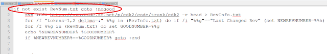 Now that AutoBuild.bat can build the latest revisions of EDK2 on a daily basis, we need to make sure that AutoBuild.bat only builds EDK2 if it finds a revision of EDK2 that it has not built before. To check if it has built a certain revision, AutoBuild.bat searches to see if RevNum.txt exists. RevNum.txt contains the revision number for the last revision to be built. If RevNum.txt does not exist, AutoBuild.bat has not built a revision before, so AutoBuild.bat immediately starts downloading and building the latest revision. If RevNum.txt does exist, it signifies that a previous revision has been built.
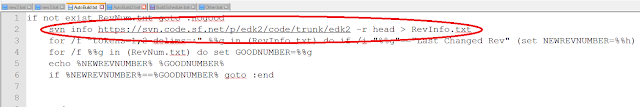 AutoBuild.bat uses svn info in order to get the revision number of the latest revision of EDK2 uploaded to Subversion.
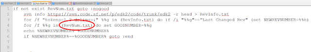
AutoBuild.bat also uses RevNum.txt to get the revision number of the last EDK2 revision built by AutoBuild.bat.
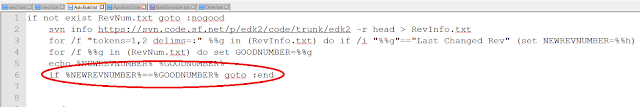
AutoBuild.bat then checks to see if the revision number in RevNum.txt is equal to the revision number of the latest revision. If they are the same, AutoBuild.bat doesn't build the revision because it already has built it. Otherwise, AutoBuild.bat downloads the new revision of EDK2.
To set up AutoBuild.bat, follow the instructions in Part 1.
Schtasks
To schedule AutoBuild.bat, you will need to call SCHTASKS in the Command Prompt. To set up AutoBuild.bat's schedule correctly, use the following structure:
schtasks /create /sc daily /tn taskname /st HH:MM /tr "c:\sourcecode\AutoBuild SenderEmail SenderPassword RecieverEmail SMTPServer"
In the line above, taskname is the name assigned to the schedule. HH:MM is the time when AutoBuild.bat will run. Schtasks uses 24-hour time, so 11:00am should be written as 11:00 and 11:00pm should be written as 22:00.
If any of the arguments passed into the /tr section of schtasks have spaces, use the following structure when writing the /tr section:
/tr "\"c:\sourcecode\AutoBuild\" \"argument1 with spaces\" argument2"
The schedule frequency, or /sc, is currently set to daily. If you want to change the frequency, all other valid /sc inputs can be found here.
The following line shows an actual example of using schtasks:
schtasks /create /SC daily /TN BuildSchedule /ST 11:00 /TR "c:\sourcecode\AutoBuild2 sender@email.com MyPassword1 reciever@email.com smtp.email.com"
The following line shows an actual example of using schtasks:
schtasks /create /SC daily /TN BuildSchedule /ST 11:00 /TR "c:\sourcecode\AutoBuild2 sender@email.com MyPassword1 reciever@email.com smtp.email.com"
Checking Conditions
 Now that AutoBuild.bat can build the latest revisions of EDK2 on a daily basis, we need to make sure that AutoBuild.bat only builds EDK2 if it finds a revision of EDK2 that it has not built before. To check if it has built a certain revision, AutoBuild.bat searches to see if RevNum.txt exists. RevNum.txt contains the revision number for the last revision to be built. If RevNum.txt does not exist, AutoBuild.bat has not built a revision before, so AutoBuild.bat immediately starts downloading and building the latest revision. If RevNum.txt does exist, it signifies that a previous revision has been built.
 AutoBuild.bat uses svn info in order to get the revision number of the latest revision of EDK2 uploaded to Subversion.

After checking for new revisions, AutoBuild.bat runs as described in Part 1. Using schtasks for EDK2, you can create a schedule for AutoBuild.bat and send error messages to the people who created the bad revisions of EDK2. This can help to more efficiently monitor and manage revisions of EDK2.
Tuesday, August 20, 2013
Automatic Build Programs - Part 1
Because EDK2 is opensource, people around the world are constantly updating its code. Managing EDK2's thousands of revisions can be difficult. This article discusses the program AutoBuild.bat, which helps to simplify the revision management process for EDK2.
AutoBuild.bat has three major steps. First, the program downloads the latest version of EDK2 from Subversion. After that, AutoBuild.bat builds the EDK2 environment. The third function is to email an error message if the EDK2 environment could not build. The email will also attach enough information for the receiver to begin fixing the bug.
This article assumes that the folder c:\sourcecode exists.
 After Blat has been downloaded, open the folder containing Blat's contents and select the folder "blat311".

Within the "blat311" folder, open the folder "full." Select blat.exe and copy it by pressing Ctrl+C.

Go to the folder c:\sourcecode and paste blat.exe by pressing Ctrl+V. This will allow AutoBuild.bat to use Blat while running. This article discusses the configuration of blat later on.
 After SysLib is downloaded, you can find AutoBuild.bat inside the folder "Tools" within SysLib. In order to run, AutoBuild.bat must be moved out of this folder into c:\sourcecode because all contents of c:\sourcecode\edk2 are deleted when AutoBuild.bat is run, and if it is not moved, AutoBuild.bat will delete itself from c:\sourcecode\edk2 as well.

If you decide that you want to change the directory for EDK2 to be download to, open AutoBuild.bat, and replace every instance of c:\sourcecode\edk2 with the desired directory.
 If you downloaded Blat to a folder other than c:\sourcecode, open AutoBuild.bat, and replace every instance of c:\sourcecode with the desired directory. Remember to copy blat.exe and AutoBuild.bat into the new directory.
NOTE: If you want to change both the EDK2 download directory and the Blat directory, change the EDK2 download directory first.
 If the SMTP Server Address does not use the standard port number, open AutoBuild.bat. Near the bottom of the file, on the line starting with "blat", the word -port is written followed by a number. This number is the port number that Blat uses to connect to the email server so it can send an email. Replace the written port number with the port number for the SMTP server that will be sending the email, then save AutoBuild.bat.


Before building, AutoBuild.bat sets the work space and build environment for EDK2. The program sets the work space to c:\sourcecode\edk2, and initializes the build environment by calling edksetup.bat.

After setting up the build environment, AutoBuild begins to build EDK2. All build information is sent to the file BuildLog.txt.

While building, the build process sets the variable %ERRORLEVEL%. If %ERRORLEVEL% equals zero, no errors occurred during the build, otherwise, there was an error during the build process. AutoBuild uses the %ERRORLEVEL% to determine whether a build was successful or not.

If the build was successful, AutoBuild uses svn info to retrieve the information on the revision that was just built and save it in the text file BuildInfo.txt. AutoBuild.bat searches through BuildInfo.txt until it finds revision number. The information on that revision is then appended to BuildLog.txt. The revision number is then saved into the file GoodRevision.txt.

If the build produces an error, AutoBuild uses svn info to get the information on the revision. The program saves the revision number into OtherInfo.txt. AutoBuild then tests to see if the file GoodRevision.txt exists. If GoodRevision.txt does exist, the program uses svn log to get the information on each revision since the last successful build. The program appends the information to BuildLog.txt. If GoodRevision.txt doesn't exist, the current revision is set as GoodRevision.txt. The revision's information is still appended to build log, but the statement "No previous successfully build revision could be found." is also appended to BuildLog.txt.
 After the information has all been appended to BuildLog.txt, Blat is called to send an email to the specified email address. BuildLog.txt is attached to this email as well.
AutoBuild.bat has three major steps. First, the program downloads the latest version of EDK2 from Subversion. After that, AutoBuild.bat builds the EDK2 environment. The third function is to email an error message if the EDK2 environment could not build. The email will also attach enough information for the receiver to begin fixing the bug.
This article assumes that the folder c:\sourcecode exists.
Blat
AutoBuild.bat emails an message to a specific address after EDK2 has been parsed. To send this email, AutoBuild.bat uses the program Blat. Blat must be download from blat.net before AutoBuild.bat can be run.
 After Blat has been downloaded, open the folder containing Blat's contents and select the folder "blat311".
Within the "blat311" folder, open the folder "full." Select blat.exe and copy it by pressing Ctrl+C.

Go to the folder c:\sourcecode and paste blat.exe by pressing Ctrl+V. This will allow AutoBuild.bat to use Blat while running. This article discusses the configuration of blat later on.
AutoBuild.bat
To get AutoBuild.bat, download SysLib using Subversion from the following link: https://svn.code.sf.net/p/syslibforuefi/code/trunk
 After SysLib is downloaded, you can find AutoBuild.bat inside the folder "Tools" within SysLib. In order to run, AutoBuild.bat must be moved out of this folder into c:\sourcecode because all contents of c:\sourcecode\edk2 are deleted when AutoBuild.bat is run, and if it is not moved, AutoBuild.bat will delete itself from c:\sourcecode\edk2 as well.
If you decide that you want to change the directory for EDK2 to be download to, open AutoBuild.bat, and replace every instance of c:\sourcecode\edk2 with the desired directory.

NOTE: If you want to change both the EDK2 download directory and the Blat directory, change the EDK2 download directory first.
Using AutoBuild.bat
AutoBuild.bat is called from the Command Prompt using the following structure:
AutoBuild SenderEmail SenderPassword RecieverEmail SMTPServer
AutoBuild SenderEmail SenderPassword RecieverEmail SMTPServer
In the above line, SenderEmail is the email address that the error message will be sent from. SenderPassword is the password for the sending email address. RecieverEmail is the email that will receive the error message. SMTPServer is the SMTP server address for the sending email address.
 If the SMTP Server Address does not use the standard port number, open AutoBuild.bat. Near the bottom of the file, on the line starting with "blat", the word -port is written followed by a number. This number is the port number that Blat uses to connect to the email server so it can send an email. Replace the written port number with the port number for the SMTP server that will be sending the email, then save AutoBuild.bat.
 The AutoBuild Process

AutoBuild.bat begins by deleting the folder c:\sourcecode\edk2, and all its contents, if it exists. AutoBuild then recreates c:\sourcecode\edk2. The program calls svn checkout, which repopulates c:\sourcecode\edk2 with the latest revision of EDK2 found at https://svn.code.sf.net/p/edk2/code/trunk/edk2.


While building, the build process sets the variable %ERRORLEVEL%. If %ERRORLEVEL% equals zero, no errors occurred during the build, otherwise, there was an error during the build process. AutoBuild uses the %ERRORLEVEL% to determine whether a build was successful or not.


If the build produces an error, AutoBuild uses svn info to get the information on the revision. The program saves the revision number into OtherInfo.txt. AutoBuild then tests to see if the file GoodRevision.txt exists. If GoodRevision.txt does exist, the program uses svn log to get the information on each revision since the last successful build. The program appends the information to BuildLog.txt. If GoodRevision.txt doesn't exist, the current revision is set as GoodRevision.txt. The revision's information is still appended to build log, but the statement "No previous successfully build revision could be found." is also appended to BuildLog.txt.
 After the information has all been appended to BuildLog.txt, Blat is called to send an email to the specified email address. BuildLog.txt is attached to this email as well.
This post sets up the basic ideas and principles behind an automatic build program. A later post will discuss how to create a schedule for AutoBuild.bat.
Subscribe to:
Posts (Atom)


