UEFI News and Commentary

Sunday, February 19, 2017

The UEFI Maze Game, Part 4

This is the fourth part of our series on a simple maze game built as a UEFI shell application. The first three parts discussed the main application, game loop and maze generation. This time, I will focus on UEFI's Graphics Output Protocol (GOP) and loading and decoding bitmaps from files.

The first part searches for the instances of the Graphics Output protocol in the system, chooses the one where the maze will be displayed and stores a pointer to it in a global variable.

Figure 1 - Find the Graphics Output Protocol, Bitmap.c

Line 25-35

Find all instances of the Graphics Output protocol that are available in the system. There can be one instance per graphical device in the system. Each one of the instances can be set to a different resolution and support a different number of colors. Rather than requiring the application to manage all of the devices, most systems use the Console Splitter driver, which acts as a meta-driver, aggregating the information from all of the drivers and drawing all bitmaps on all displays. The LocateHandleBuffer() function in the UEFI Boot Services allocates a buffer to hold all of the handles that support a specified protocol. 

Lines 37-46

Now that we have found handles for all drivers that support the Graphics Output protocol, we examine each handle to see if it also has an instance of the Device Path protocol. Why? Because the one way to distinguish the Console Splitter from all other graphical devices in the system is that it is not actually a hardware device. Since it is not a hardware device, it does not have a Device Path protocol associated with it, since the Device Path protocol used to describe how a device is attached to the system. If we find a handle that doesn't have an instance, the pointer to that instance of the Graphics Output protocol is saved in a global variable.

Lines 47-53

Now we just have to clean things up and return. First, we free the buffer that the system allocated when we called LocateHandleBuffer. Then, we check whether we found a Graphics Output protocol instance that meets our need and return TRUE if we did and FALSE if we did not.


Now, in the next section, we're going to dive into the meat of converting a buffer formatted as a Bitmap (BMP) into a format that can be used with the Graphics Output protocol.

Figure 2 - Converting .bmp Files to Graphics Output format, Bitmap.c

Lines 73-83

On entry, this function takes a buffer that is formatted following the BMP format (see here for more information), along with its size. On output, this function returns a pointer to an array of pixels (GopBlt), the size of that buffer in bytes (GopBltSize). The pixels are divided into PixelHeight rows, with each row containing PixelWidth pixels. Each of the output pixels is formatted as a EFI_GRAPHICS_OUTPUT_BLT_PIXEL structure. This structure has 8 bits for red, green and blue, and 8 reserved bits, making 32-bits per pixel.

Lines 85-98

These are the local variable declarations. BmpHeader and BmpColorMap are pointers to structures that are part of the BMP specification. The EDK2 implementation stores these structures in MdePkg\Include\IndustryStandard\Bmp.h.

Lines 100-104

A simple sanity check makes sure that the buffer passed in at least has the number of bytes required to hold the standard BMP format header structure. 

Figure 3 - Perform Sanity Checks on the BMP Header, Bitmap.c

Lines 106-108

Another basic sanity check is so see if the first couple of bytes in the file have the signature 'B' and 'M'. 

Lines 110-123

This function doesn't support all of the various sub-formats described in the BMP specification. For example, it doesn't support any of the compression formats or any of the extended headers.

Lines 125-137

This function then checks to see whether the data is 4-byte aligned, relative to the start of the buffer. Also, the remaining size of the buffer after the header should be equal to the size of the bitmap as specified in the bitmap header.


Lines 139-146

The color map translates bytes in the bitmap buffer portion of the BMP format into actual colors. The pixels in the bitmap are packed as 1-bit per pixel (2 colors), 4-bits per pixel (16 colors), 8-bits per pixel (256 colors) or the default (24-bits per pixel). The color map translates the bits-per-pixel in the bitmap into actual colors. So 0 might be black, but 1 might be blue (not black) and 2 might be green, etc.  

Lines 148-166

The number of pixels determines the size of the color map. So 1-bit per pixel has two possible color map values (0 and 1) while 4-bits per pixel has 16 possible color map values (0, 1...15). If there are 24-bits per pixel, then no color map is needed. The color map appears between the BMP header and the actual bitmap, so the function performs a sanity check to make sure that the color map is the right size.

Lines 168-172

Now the temporary Image and ImageHeader are set to the beginning of the image within the BMP format. Image will be incremented as pixels are processed while ImageHeader remains unchanged.

Figure 5 - Allocate Buffer to Hold Returned Bitmap, Bitmap.c

Lines 174-184

The function determines how much memory will be required to hold the returned bitmap based on the vertical and horizontal dimensions of the image. A sanity check makes sure that this doesn't result in multiplied value that is ridiculously large.

Lines 186-205

If the user passed in a buffer pointer via GopBlt, then try to use that buffer, as long as it is large enough. This improves performance by reusing a buffer, where possible. If it isn't large enough, it returns the EFI_OUT_OF_RESOURCES error to let the caller know the buffer was too small and returns the size that would be required. If the user did not pass in a buffer pointer via GopBlt, then the function allocates a buffer that is large enough. 

Lines 207-208

Now that we have the buffers, and the size, set the return size in pixels.

Lines 210-215

This outer loop cycles through all of the rows in the input image buffer, setting Blt to the first pixel in the output row. 

Line 216

This inner loop cycles through all of the packed pixels in an input image buffer row.

Line 217

Each of the following switch case statements deals with one way of packing pixels into bytes. Each of the case statements is responsible for leaving the loop counter Width and the output buffer pointer Blt in the correct location for the next iteration of the inner loop. 

Lines 218-232

This section handles the case whether there are 8 pixels packed in a single byte in the input image buffer. The loop works through all 8 bits, isolating the pixel value and then translating it to a full GOP pixel value in the output buffer using the color map.


Lines 234-250

This section handles the 4-bits per pixel case, where two pixels are packed into a single byte. Each half of the byte is translated into a pixel in the output bitmap using the color map. There is a special check for the case when there are an odd number of pixels on a line and this is the last byte in the input image buffer.

Lines 252-259

This section handles the 8-bits per pixel case, where a single pixel is packed into a single byte. Each byte is translated into a pixel in the output bitmap using the color map.

Lines 261-268

This section handles the 24-bits per pixel case, where a single pixel is packed into three bytes. No translation is done with the color map, since it is already in full color encoding. 


Lines 270-280

This section handles the case when the bitmap header specified anything other than 1, 4, 8 or 24-bits per pixel. In this case, buffers are freed and an error status code is returned. 

Lines 284-291

After finishing a single row, the input buffer pointer is bumped up to the next 32-bit boundary.

Line 293

At this point, we're all done and have a completely decoded bitmap.


The next section loads any file into memory.

Lines 297-303

This function loads an entire file into memory. On entry, the caller provides the path of the file. Since this is a shell application, the caller can use mappings such as FS0, FS1, etc. On exit, this function returns a pointer to the buffer containing the entire file's contents and the size of the file, in bytes.

Lines 305-308

Using the standard C library functions, the file is opened. If there is a problem, an error is returned.

Lines 310-312

Now that the file is open, see to the end in order to determine the file's size. Then return back to the start.

Lines 314-317

Now allocate a buffer large enough to hold the entire file, using the file size calculated.

Lines 319-322

Read the entire file into the allocated buffer, close the file and return.


Now we will wrap up this article with a helper function that uses all of the pieces we've introduced so far. This function reads a file into memory, converts it into a Graphics Output protocol bitmap, and then frees the allocated memory for the file.

Lines 327-333

On entry, the caller provides the path of the BMP format file to convert. On exit, this function returns a pointer to the bitmap, and the bitmap's width and height.

Lines 335-343

First, load the file into an allocated buffer.

Lines 345-357

Now convert the file into a GOP style bitmap.

Lines 359-360

Now free the memory occupied by the file (but not the bitmap) and return success.


Now we have come to the end of our little program. The files will be checked into the sourceforge repository in the next week.


Thursday, January 12, 2017

Firmware Bugs and Firmware Updates

My co-author and partner in various things UEFI, Vincent Zimmer, has penned some wise words about how firmware bugs are perceived on his blog (here). He quotes the first chapter of Embedded Firmware Solutions wherein an anonymous manager states, "If you can fix a hardware bug in firmware, it’s not a bug but a documentation issue."

What Vincent said about hardware used to be the same for operating systems. That is, it was often hard to (a) convince an OS company that they had a bug, (b) get them to fix that bug and (c) get that fix out to customers. But now, Patch Tuesday is a weekly event, monitored by websites everywhere. The OS images used by OEMs can have hot-fixes applied. So, now the situation is fixed. Hardware is the hardest to fix, followed by firmware, followed by the OS, followed by applications.

That is why firmware update has been a major focus of the recent UEFI specification updates, standardizing how 3rd party components can produce and process updates (c.f. capsules and the Firmware Management protocol, ESRT). These updates are not only for the system firmware's flash device, but also for the embedded flash on smaller chips, as well as attached USB and PCI devices. Security concerns, in particular, are driving the need for reliable and timely updates of all of these.

The next frontier is delivery of these firmware updates via the OS. While there has been some progress here by the OS vendors (Redhat, Microsoft, Canonical, see older summary here), there seems to be reluctance on the part of some OEMs. Part of this is that some of their unique value(if you can call the little tray icon apps "value") is getting sucked into the OS. Part of this is relying on the process by a 3rd party (or more than one 3rd parties) to deliver updates. Part of this is: older, out of production platforms aren't interesting any more. But highly publicized hacks and bugs are putting pressure on the industry to solve the distribution problem.

Whatever the case, platform stability rests solidly on firmware stability because of its unique capabilities to fix or mitigate hardware and OS issues, as testified to by Marvel's Agents of SHIELD.

Saturday, December 03, 2016

The UEFI Maze Game, Part 3

This is the third part in a series of posts about a simple game written as a UEFI Shell application. It consists of generating a random graphical maze and navigating a little man through that maze from entrance to exit.

This post gets to the actual maze generation, which is actually a recursive function. Pick a random position. Then pick a random direction and, if that cell is completely surrounded, then mark the cell as a path. If there is no such cell in any direction, then back up. This algorithm generates that there are no circular paths through the maze.

Figure 10.40  Maze generation main function, part 1 in Game.c
Lines 272-280
This function gets called once for each grid cell. The coordinates of the current cell are X and Y.
Lines 282-288
The local variables keep track of which neighbors to the current cell. The number of valid neighbors and then the direction from the current cell. 
Lines 293-299
If the neighboring cell to the left is surrounded by walls, then it is a possible cell that we could go to next. So record the cell’s coordinates and increment the number of valid neighbors.
Lines 301-307
If the neighboring cell above is surrounded by walls, then it is a possible cell that we could go to next. So record the cell’s coordinates and increment the number of valid neighbors.

Figure 10.41 Maze generation main function, part 2 in Game.c
Lines 310-315
If the neighboring cell down is surrounded by walls, then it is a possible cell that we could go to next. So record the cell’s coordinates and increment the number of valid neighbors.
Lines 301-307
If the neighboring cell to the right is surrounded by walls, then it is a possible cell that we could go to next. So record the cell’s coordinates and increment the number of valid neighbors.
Lines 328-331
If there are no valid neighbors then we need to back track to the last valid position and try again.

Figure 10.42 Maze generation main function, part 3 in Game.c

Lines 336-340
Pick a random direction and update the coordinates in that direction.
Lines 343-345
Save the coordinates in the backtrack list.
Lines 349-357
Mark the maze in that direction as a path and increment the number of cells visited.
Lines 361
Now recursively call this function, but this time start at the next location.

Next Steps

Now the finish line is nearly in sight. We have the environment, we have the bitmaps, and we have the maze. Now we just need to draw it and move the man around.

Oh, wait. We haven't seen how to read the bitmap files or draw them with transparency. These functions are not provided within UEFI itself, so we will add them in a single post!

Tuesday, November 22, 2016

The UEFI Maze Game, Part 2

This is the second article in a series describing a simple UEFI Shell game that generates a random maze and lets you navigate a character through that maze to the exit. The goal is to show how to use graphics and the UEFI Shell together, line by line.

The next step is to initialize the grid and the maze. The maze uses two-by-two sections of the grid. These sections can have one of the following configurations


Notice that in each chase, the lower-right cell is always a rock, and the upper-right cell is always empty. The only question is whether there is a pathway to the right, to the bottom, or both.

Figure 35

Lines 407-423
This function divides up the screen into cells based on the size of the loaded bitmap images. If there aren’t e

nough cells to make a reasonable maze then the function exits with an error. The maze uses a two by two section for each part of the maze. In addition, the first row and first column must be all walls. This means that the number of rows and columns must be odd. 
Lines 425-434
The function creates the buffer for the maze bitmap.
Lines 436-441
The function creates the buffer for the maze grid contents.

Figure 36
Lines 443-448
Initialize every cell in the grid to a background image.
Lines 450-451
Display the empty background grid. This is important, because the other images (rock and player) need to be drawn on to another color besides black.
Lines 454-460
Initialize the maze generation data structures, create the random maze, copy that maze over to the grid and then free up the allocated data structures.
Lines 462-469
The entrance is at a random location on the top edge. The exit is at a random location on the bottom edge.
Lines 471-475
Now move the character to the entrance and draw it on the bitmap. 

During maze initialization, we create a temporary grid.


Figure 37
Lines 231-242
The temporary two-dimensional array mMaze holds either PATH or WALL for every location.
Lines 245-259
The backtrack arrays are used so that when we get to a dead end, the maze generator can back up to the last place where a decision was made.
Lines 261-269
Since in every 2x2 section of the maze, the bottom right cell is a rock wall, set that now.

These utility functions simply make it easier.


Figure 38

Lines 195-200
These global variables hold the maze and the backtrack data structures. The maze (mMaze) is a two-dimensional array where each element is set to either a path (PATH) or wall (WALL). The backtrack arrays contain the coordinates in the maze of the last point where a decision was made.
Lines 202-207
Utility function to return what is at a specific set of coordinates in the maze.
Lines 209-214
Utility function to change what is at a specific set of coordinates in the maze.
Lines 216-226
Utility function that returns whether there are walls in all four directions.

Now there are the two functions to generate the maze and shutdown the maze.

Figure 39


Lines 380-385
This function calls the maze generation function, starting at the upper-left hand cornder of the maze. Since each maze cell requires a 2x2 section of the grid, we divide both the height and width of the grid by 2. We subtract 1 because we leave one extra for the wall on the top and left of the grid.
Lines 389-394
Free up all of the resources used by the maze generation.
Next Steps
Now we have all of the pieces we need to generate the maze and all the parts to draw it. In the next article, we'll dig in to the heart of the maze generation function.

Sunday, November 13, 2016

The UEFI Maze Game, Part 1

This UEFI Shell application features a very simple maze game that uses UEFI’s Graphics Output protocol to draw a random maze and direct a character from entrance to exit using a keyboard. It will be added to the SVN repository after the last article in this series is published.

This application features a few nifty touches, including converting bitmap (.bmp) files to HII, merging bitmaps using transparency and a nifty maze generation algorithm. This application uses both the standard C library, as well as UEFI-specific libraries.


This game doesn’t have any villains or time limits, yet. Originally, I planned to integrate the thermometer application previously discussed so that the main character got hotter and hotter and little ice cubs in the maze would cool him down. You can add villains in the maze, or the animation could move smoothly from cell to cell or there could be some sort of time limit.

The source is spread over two .C files. It also uses three bitmap files, which are included in the online source code. These bitmaps are: a rock, a player, and a solid green background.

The First Source File: Game.c
Figure 1: Global Variables in Game.c
Lines 1-13
These are the include files for the standard C library, basic UEFI services and, surprise(!) bitmaps. The MdePkg\Include\IndustryStandard contains constants, data structures and file formats from many popular industry standards, including PCI, ACPI and USB.
Lines 15-41
These are the key function declarations from the other source file, Bitmap.c. Rather than create a separate header file, they are just listed here.
Figure 2: Game State Data in Game.c


Next we move on the various global variables that maintain the game state.


Lines 46-47
DisplayImageStack is the global function that refreshes the screen from the internal buffer that holds the game’s bitmap image.
Lines 50-51, 64-65
These globals hold the width of the loaded background images and other images. These should be the same.
Lines 52-54
These point to the three bitmaps used in the game: the rock, the background and the player. Each is 50 x 50 pixels.
Lines 56-58
The game maintains a pixel-for-pixel copy of what is actually going to be displayed on the maze portion of the screen.  All of the player actions are updated here before they are copied to the screen. 
Lines 60-62
The game also maintains a cell-by-cell copy of what is in each part of the grid. The array mGrid contains a two dimensional array, mGridWidth cells wide by mGridHeight cells tall. Each element in the array points to one of the bitmaps: rock, background or player. The size of the array is calculated based on the screen resolution.
Lines 67-74
These mark the coordinates (within mGrid) of the character’s position, the entrance position and the exit position. Initially, the character’s position is at the entrance position. The game ends when the character reaches the exit position.
Figure 3 Game entry point in Game.c

Now that you are thoroughly bored with the global definitions, we finally reach the entry point of the game. 

Lines 590-596
This uses the standard C-style entry point. But there are no command-line options parsed.
Line 598
The srand() function is used to initialize the random number generator with a seed value. In this case, the seed value is derived from the system time. When debugging the maze generation algorithm, it was useful to set this to a fixed value so that the maze would be the same each time, facilitation easier debugging of issues.
Line 600
Reset the console so that the screen is empty.
Lines 602-606
Load all of the bitmap images and convert them into the format used by the UEFI graphics output functions. If there is an error, it means that not all of the images could be loaded or (less likely) the system cannot switch to graphics mode.
Line 608
Initialize the game data structures, including the maze.
Line 610-614
Display the maze for the first time.
Line 616
Enter the main game loop. This loop continues until the user indicates they are finished or they have reached the maze exit.
Line 619-621
Clear the screen and exit.

Figure 4 Setup bitmap images and Graphics Output Protocol in Game.c

The first step for the game is to load all of the bitmaps out of the files.

Lines 108-110
Find the instance of the UEFI Graphics Output protocol.
Lines 112-127
Load each of the three bitmaps from external files. Each of the files is formatted using the industry standard .bmp file format. 

Next Time
In the next installment, we'll look at exactly how to initialize UEFI's Graphics Output Protocol and load a bitmap.

Wednesday, October 26, 2016

Intel and Insyde Embedded White Paper

Stephen Gentile, my colleague at Insyde Software, and I wrote a white paper with several Intel IoTG folks that describes how our UEFI-based embedded solution, BlinkBoot®, solves real-world business and technical challenges. You can find the paper here. BlinkBoot includes a unique add-on technology model, called Lenses, and a dedicated suite of tools: BlinkDebug, BlinkFlash and BlinkShell.


Thursday, October 20, 2016

PI 1.5 Released

This is late news, but you should head on over to the UEFI web site and pick up the PI 1.5 specification (here). Here are the highlights:

  1. Change the term System Management Mode (SMM) to Management Mode (MM)
  2. Provide a Management Mode infrastructure on ARM systems by using TrustZone.
  3. Allow initialization of Management Mode, as early as SEC or PEI. Also introduced a new class of MM drivers that launch natively within MM.
  4. Improved I2C support.
  5. Allow SEC to pass HOBs to PEI.
  6. New multi-processor protocol 
  7. Updated Disk Info to support SD/MMC
  8. and more...
As you can see, SMM (or rather MM) was a big part of this update. I started this, but my efforts were dwarfed by others. Part of the reason was that the ARM 64-bit folks had already started down a standardization path for TrustZone and it required some diligent technical and consensus-building work to create an environment that both ARM and x86 architecture firmware could share. We didn't just include Aarch64 systems. We made IA32 and X64 systems more robust and flexible as well. A shout out to Charles Garcia-Tobin (ARM) and Vincent Zimmer (Intel) on this.


Friday, October 03, 2014

Security to Eclipse User Features as Top 2015 Firmware Story

I stepped out on a limb this year and made a prediction. Predictions are notoriously fraught with peril and I am usually off-base or overly optimistic in mine. Nonetheless, as CTO of Insyde Software, I guess its also an unenviable part of my job. So here it goes:
'security' will eclipse 'lost my password', 'can't flash my BIOS' and 'overclocking' as the top firmware story in 2015.
For each of the previous hot firmware topics, the focus was on the user doing something correctly or incorrectly. The assumption was: if you don't do something dumb, your system will be ok.  Now, with security: even if the user doesn't do something dumb, it is possible that the system is not ok.

The OEMs (and firmware vendors) are now find themselves in the hot seat. Recent Black Hat presentations have increasingly focused on the vulnerabilities to be found in open source and closed source firmware implementations. Since firmware occupies such a privileged position in the software stack, successfully compromising it opens up a world of malware possibilities. With UEFI, the firmware has also become more capable and standardized, so more resources are theoretically available

The UEFI Forum has recognized this for a while and responded by creating a flexible OS secure boot and secure firmware update strategy in version 2.4 of the specification. The various software initiatives (including the open source ones) have followed quickly behind to implement these standards. But the security researchers and hackers began picking those apart, looking for and finding corner cases.

So the UEFI Forum responded by creating the USRT (UEFI Security Response Team), headed up by friend and former colleague, Dr. Dick Wilkins. The USRT provides a single point of contact for researchers to report their findings and disseminate those to silicon, software and system vendors.

At the same time, various UEFI Forum members, including Intel and my own company, Insyde Software, are producing domain-specific tools to test for certain well-known classes of vulnerabilities that are specific to our products. Intel has announced support for the CHIPSEC tool which evaluates the register settings in the motherboard chips to see if they are correctly configured to protect the firmware and boot process. Insyde is working on tools which check the various runtime interfaces we provide (and which OEMs extend) for classic API issues including buffer overflow and pointer validation.

Both UEFI's USRT plans and current firmware security tools will be discussed at the upcoming UEFI Plugfest, which is coming to Taipei from 13-17 October.

No one wants their company name featured in a security vulnerability press release. We'll talk again next year and see if my prediction is right.


Wednesday, September 03, 2014

New BIOS-Related Blogs

The first one is by my former colleague at Phoenix, Count Chu. He has already put together a number of interesting articles on parsing PDB files and the Design Pattern of the Report Status Code infrastructure.

The second is by William Leara, a BIOS developer at Dell, who writes on various topics of interest to BIOS developers (as the URL http://www.basicinputoutput.com/ might indicate), including using the UDK2014 and beautifier tools on EDK2.

Add this to Vincent Zimmer's intricate musings on firmware, security and technology in general on his blog and you have a pretty robust set of guru resources on BIOS.

Tuesday, August 19, 2014

ARM, Servers and the Shrink-Wrap OS

ARM just released the Server Base Boot Requirements document (more info here) which "defines the ARMv8 platform firmware abstractions necessary for OS deployment and boot, HW configuration and management, and power control" for servers that follow their SBSA specification. This is an important step so that OS vendors, like Red Hat and Microsoft, can produce "standard" operating systems distributions that work on any SBBR-compliant system.

What do you need to boot? Well, first of all, the operating system needs to detect all of the undetectable devices on the platform without a lot of poking and probing. That's because the standard OS image can only support a limited number of interrupt controllers, CPU memory management schemes, and high-resolution timers. So its a good idea if everyone can agree on a standard hardware architecture for these devices or, if not, a standard abstraction for how to talk to them. You don't want to use kernel configuration files, because that requires that the OS image is not the "standard" OS image, but rather one which has been modified for a specific SoC or specific board. So SBBR recommends the new ACPI 5.1 specification. People may not remember this, but one of the things that ACPI does (the "Configuration" part of the acronym) is provide a way to describe the hardware resources (memory, I/O, IRQ, DMA, etc.) used by non-enumerable devices and providing an identifier that the OS can use to load a specific device. The ACPI 5.1 specification did a few tweaks to that basic model for new ARM devices, but the same ideas are still valid.

Next, the operating system needs to be able to talk to the boot device long enough for it to be able to get its own drivers loaded. It is a sort of contract where the firmware finds the OS loader, validates it, and then jumps into it. But that OS loader then needs to load other files. Now it can try to put everything into a massive super-loader that can handle every device known to man or woman, or it can ask the firmware to read those files. That's why SBBR recommends UEFI 2.4, because UEFI has a well-defined mechanism for handing off control to OS loaders, loading files and then cleanly handing over control of devices to an OS driver.

How does the OS find out more information about the platform? Manufacturer name? DIMM types? Platform UUID? SBBR recommends the SMBIOS specification, version 2.8.0, published by the DMTF , which "addresses how motherboard and system vendors present management information about their products in a standard format" (see DSP0134).

Finally, ARM CPU cores can be arranged in a bewildering array of topologies, with an amazing variety of power states, can be described by the PSCI interface (from ARM and ACPI). This interface allows the interface to manage the tricky business of manipulating individual cores and managing the dependencies between them.

All of these work together to support the shrink-wrap experience. The goal: one DVD or one OS image can boot the system enough to get to the net and download any other updated or missing pieces. So standards that provide the pieces so that I can get my system to that point based on the information built into the firmware make everyone's job easier.


Tuesday, August 12, 2014

UEFI Forum releases the ACPI 5.1 Specification

For years, the ACPI specification was developed by what was essentially a 5-way tangle of an IP agreement between Microsoft, Intel, Toshiba, Phoenix and HP. It was a closed group with no simple way for new ideas and direction from outside.

After ACPI 5.0 was released, it became clear that if ACPI were going to have wider industry adoption, it would need to open up to a different sort of development process. At the UEFI board meetings (when I was with Phoenix), I saw most of the same companies and most of the same people as with ACPI. After much discussion between companies with large contingents of lawyers, the UEFI Forum took over management of ACPI and the UEFI board created the ASWG (ACPI Specification Working Group) to manage ACPI's development.

One of the first challenges after this change in management was to clean up the ACPI specification and make it more ARM AArch64 friendly. ACPI 5.0 had already paved the way with the Hardware-Reduced profile, removing many of the assumptions about hardware registers, processor states and bus hierarchies . These had been driven to some extent by Microsoft when Windows RT was on the horizon. For a description of the ACPI-related changes made by Linaro and other ARM partners, see this summary. Linaro has been very active in submitting kernel patch after kernel patch to modify the X86-only flavor of some of the Linux kernel pieces.

Now, with the release of the new ACPI 5.1 specification in a timely fashion, the remaining bits that didn't fit have been cleared away. There is still more work to be done, but at least Linux, ACPI an ARM have a clear path forward, both in terms of technology and open specification governance.

Thursday, June 19, 2014

Update to Setting Up the EDK2's Windows-Hosted UEFI Environment With Visual Studio 2012

Some of the building components and file names of EDK2 have been update. The article HOW-TO: Set Up the EDK2's Windows-Hosted UEFI Environment With Visual Studio 2012 has been updated to accommodate this.

Click here to view the article.

Tuesday, June 10, 2014

UEFI and SoCs and Chipsets and Firmware Complexity

When I switch back and forth between Insyde's x86 and ARM partners, I have to do a mental vocabulary switch. In the x86 world, we talk about "chipsets" but in the ARM side its almost universally "SoCs" Part of this is historical: the NEAT chipset was, in fact, a set of 3 chips that went alongside of the Intel CPU. More recently, there has been a traditional division of labor between the north bridge (memory controller) and south bridge (I/O controller). This split allowed CPU, memory and I/O technologies to progress at different speeds and allow for different pairings to meet different market requirements. But in the ARM world, the term SoC (system-on-a-chip) is recognized as a single-chip packaging of a CPU and all of the attendant hardware bits that are needed. New technology? Just spin a new SoC. The X86 world has responded with single-chip solutions, but the term 'chipset' still dominates.

In many ways, this difference in philosophy is reflected in firmware architectures. UEFI is designed for many hardware pieces, likely from different vendors, are combined together to boot an operating system. The fundamental unit of UEFI is a driver (or a module if you include PEI and you're a grognard for terminology). You add drivers for specific chips and attendant technologies. You remove drivers that you don't need. Seems logical, right?

But as gate density has increased, the number of technologies that can be stuffed into a single chip has also increased. Then the number of UEFI drivers increases. The difference can be startling: the number of modules (libraries, drivers and modules) required to support one chipset can be 10x more than the number required to support another.

Is this reasonable? If I have one chip on the motherboard, it seems reasonable that I should add 1 thing (driver, module, package, whatever) to the build. That would be my ideal world.

Indeed, there are initiatives going that direction. My friend, Intel guru Vincent Zimmer recently wrote about Intel's FSP (Firmware Support Package) on his blog. The FSP attempts to hide some of the complexity by packaging up most of the chip-support firmware into a single binary blob with three entry points. Dig a little deeper and you find that this "blob" is really a specially formatted UEFI firmware volume with PEI drivers (aka PEIMs). But, along with binary editing of board-specific options, it provides a good starting point to answering the objections of silicon-related firmware complexity. It still struggles with all of the traditional problems of binary deliverables, such as debugging and hot fixes. And it doesn't solve everything for industry standards like ACPI and SMBIOS and even UEFI's own HII. Not to mention OS-specific add-ons (like those for Windows 8.1) It tries to maintain the flexibility of UEFI while simplifying the silicon vendor side of the equation. Good start.

Insyde (my company) has been pursuing this at the source code level, improving  how entire chip "packages" (an EDK2 term) come together to create the final firmware. Our goal: 1 command brings in the entire support for a chip. Sure, tweak it from there. Sure, highlight the couple of places where engineer input is required at build. But don't make them find a read-me. Oh, and do it the same way for every chipset/SoC because when SoCs change often, your mind spins with which/where/what in a codebase.

One of the hidden advantages of the UEFI driver model is that it works well for SoCs as well. In order to keep up with new technologies, silicon vendors keep spinning new versions of their SoCs with new sets of peripherals, new versions of memory controllers and upgraded CPU cores. Many of these SoCs share the exact same IP blocks inside, with only a few tweaks. From a firmware perspective, I'd like to grab the same piece of code and use it to support all of the SoCs in which the IP block is included. Sounds like a driver model to me, based no longer on chips on a motherboard but on IP blocks in a chip.

Longer term, that means that some firmware complexity creep is inevitable as SoCs increase in complexity. But it also means that firmware systems must improve to support the increased rate of SoC/chipset change and reduce the effort required to configure and customize those platforms. Inevitably, the BIOS guys get blamed for every delay: the motherboard is ready, the chip is ready, so why isn't the BIOS ready? Simulation (another topic) is one way. Runtime debug/log infrastructures help catch what you missed. But well-designed build systems and firmware delivery models simplify the problem up front.

Friday, April 04, 2014

The Tale of Three Conferences

This week has been a blizzard of news and announcements from three conferences that I care about, all this week. First, there was EELive! in San Jose, CA which focused on embedded systems (or, as they now like to call it, the IoT). Second, there was Intel's Developer Forum in Shenzhen, China where my company (Insyde Software) was exhibiting and speaking. Finally, there was Microsoft's Build 2014 which I was watching with avid interest with live streaming and press releases flowing. UEFI was there, to either be promoted or vilified or both, in all three.

At first glance, at EELive, you would think that no one is paying attention to UEFI. Part of this was because Intel was busy promoting FSP, touting how it could be plugged into any boot loader, including coreboot. But the Galileo board that they were showing comes with a UEFI solution. And, under the hood, FSP is really extracted firmware drivers from Intel's UEFI-based reference code, packaged in UEFI-standard firmware volume format, with a little director binary inserted to allow direct calls into the driver entry points. The other reason is that 32-bit and smaller processors still dominate the IoT space and many of those are ARM designs. ARM platform 32-bit designs have used other boot loaders traditionally, but with 64-bit ARM itself is heavily pushing UEFI as a standard boot architecture. Many discussions around UEFI have to do with complexity. And there is something to these discussions, since the very power and flexibility of UEFI has led to implementations (like that on tianocore.org) which are broken into hundreds of pieces, where assembling the right one requires the right recipes. Most embedded vendors don't need their firmware distribution to be as complicated as their Linux distribution (see yoctoproject.org).

Then there's IDF. Of course, there was the Insyde poster chat: Implementing Dual OS Solutions with UEFI FIrmware" (how to switch between two active OS sessions w/just firmware support). Intel delivered their obligatory Quark and FSP remarks. But it also put out two additional UEFI-related notes. The first appeared in the unlikely session titled "Delivering Compelling User Experiences on Intel® Platforms: Audio, Voice, Speech and Fingerprint Sensors and Biometric Authentication" But in the very back of this presentation, they talked about security issues pertinent to BIOS, including replay-attack prevention related to Real-Time Clock battery removal and secure firmware updates using the UEFI capsule update method described in the UEFI 2.4 specification. It really seemed out of place, but hey... They also recommend adding their new CHIPSEC tool, which performs security checks on chipset and firmware settings. It is available on github.

And then the Intel Android team showed their Android build tool which would create a BSP for your platform and hey, it would also customize your firmware at the same time. It leverages the Unified Binary Management Suite (UBMS), which you can see here at about the 21 minute mark. This shows the increasing co-design process required for configuring your firmware and your OS installation. Many times, the firmware and the OS need to know the same types of information about the platform. For example, which drivers to include, GPIO routing, etc. Especially on OS' that don't use ACPI and that don't rely on the firmware passing them anything (like Android).

Finally, there's Microsoft Build event. We got a definitive date for the Update 1 (with no major new BIOS requirements! Sigh of relief), Microsoft's plan to offer Windows for $0 for certain platforms, Windows booting on Quark(!). And a lot of advice about how to integrate off-SoC sensors and how to write apps that span Windows and Windows Phone.

Hard to breathe. Need air. Next week I'll have a chance to reflect further on what some of these mean. How can we take advantage of vertical integration? How can we reassure folks of security in a world where firmware is increasingly decentralized and under attack? (Did I mention EELive! had a Black Hat track???) More later....

Tuesday, April 01, 2014

Something About the Game I Made with a Thermometer In It

After making the simple app that uses composite images and transparency to change the appearance of an image based on user input (as described in this article), I decided to expand it a little into the beginnings of a simple game.  As it is now, it is simply a shell for a game, in which you can move a sprite around and change modes.

In this article, I will describe the thought process behind creating this as well as the code I wrote.  This article assumes you have read the referenced article above on composite images and transparency.

Source code for this project can be found here.

I knew I wanted this "game" to include the thermometer I had created, and have something affected by the changing temperature.  I decided I could have a little character run around the screen and his color would change with the temperature.  Because I was using the same thermometer as I did in my last project, I was able to use the same code.  The only change I made was a simple image re-size to make it a little smaller.

The next question was how I wanted the playable area to be laid out.  Would it be laid out in a grid, where each object occupied a square, or would it be free movement?  Since collision detection in a free movement environment is much trickier than a grid, I decided to lay it out in a grid.  This was a fairly easy thing to implement.

First, I created a struct to represent a square in the grid, which I called "Box."  It has it's X and Y coordinates, an array containing pointers to the adjacent Boxes in each of the four cardinal directions, and a boolean value indicating whether or not the box is occupied by an object.


The next step was to initialize the grid, which is simply an array of boxes.  So I started by clearing all the memory and initializing the first box's coordinates to (0, 0).
Now from here, I could have hard-coded all the values for every single box, but if I had decided to change the size of the grid, it would have been a big pain to rewrite, so I wrote a loop that initialized the coordinates and array of adjacent boxes for each box.  For each of the boxes, I first set it's Occupied value to false (since each box is initially empty).  I first then look in the East (right) direction to see if the box is on the right edge of the grid.  If it's not, the East adjacent box is initialized to the next box in the array, and if not, East is set to NULL.  Next, I check the North (up) direction to see if it is on the top edge of the grid.  Like the East check, I initialize the North box if it's not on the top edge, and set it to NULL if it is on the top edge. 

So along with initializing the array of boxes, we also need to initialize the coordinates, which we can do in the checks for the West edge.  We can do as we have done with North and East, and initialize the West value.  However, after that, we can begin initializing coordinates.  If the box is not on the West (left) edge of the grid, then it can base its X coordinate on the box to its left, and simply add the width of an image (which is the same as the width of a box).  Its Y coordinate is simply the same as the box to its left.  If it is a left-edge box, then its X coordinate is 0, and the Y coordinate can be gotten by adding the box height to the Y coordinate of the box above it.  Finally, we do the South check, just like the others were done, and finish initialization of the boxes.

Now I needed to deal with the images.  In this application, I had six images: the background image, the character sprite, an object sprite, and the three thermometer images.  I did the same thing as described in the articles referenced above, except with more images.  All the image setup was done in the same function, and the image buffers stored in global variables.  Details about the image setup can be seen in the previous articles or the source code (link provided above).  In the source code, I have included a miniature .FDF file that includes the additional lines I added which allow the appropriate images to be included.  In order to use this, copy the text from my .FDF file and paste it into the FILE statements section of Nt32Pkg.FDF.

The only thing I did differently with regards to image display was in ConvertBmpToGopBlt().  One of the conditions for images was unnecessarily strict, and would sometimes cause the function to falsely report an invalid bitmap image, so I removed it.  The line used to read:
if ((BmpHeader->Size != BmpImageSize) || 
      (BmpHeader->Size < BmpHeader->ImageOffset) ||
      (BmpHeader->Size - BmpHeader->ImageOffset !=  BmpHeader->PixelHeight * DataSizePerLine)) {
    return EFI_INVALID_PARAMETER;
  }
I removed the third condition so it now reads:
if ((BmpHeader->Size != BmpImageSize) || (BmpHeader->Size < BmpHeader->ImageOffset)) { return EFI_INVALID_PARAMETER; }
Which causes it to work properly.

Before we move onto the components of the actual game, we need to remember that in this game, we will be moving around a character as well as changing the temperature on the thermometer.  We could use different keys to change the temperature and move around, but I decided it would be best if the character were standing still while the temperature changed, so I made it so that the user could change which "mode" they were in, movement, or temperature change.  The mode is implemented using an enum, and stored in a global variable.

Up next is the actual character itself that the user can move around.  It contains a pointer to the buffer containing the original image, a pointer to the altered image (since we are going to change the image's color over the course of the game), its coordinates, and the box it is currently occupying.  We make the character a global variable, since there is only one.

Initializing the character struct is simple and can be done as soon as the images and grid are set up.  We first set the mode to be "MOVE" since we would like that to be the initial setting.  Image is set to point to the buffer referenced by the global variable.  The image is then copied into a new buffer, and ChangedImage points to that new buffer.  This way, ChangedImage can be altered without affecting the base original image.  Then, the coordinates and box are set to be the upper left-hand corner (just an arbitrary position).
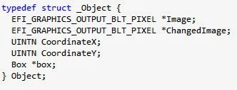
After this, I decided to have some sort of additional object on the map along with the character.  So I created a basic Object struct.  It has an Image, ChangedImage, coordinates, and box it occupies.  This is actually basically the same as the Character struct, and in the future, I could go back and combine the two into one.  There is only one non-character object in this application, but multiple objects could simply be stored in a global array.

Initializing and setting up objects is similar to that of initializing the character.  In this program, I only included one object, but it would be simple enough to expand the function to deal with multiple objects.  Like the character image initialization, we set Image to be the globally accessible buffer, and ChangedImage to be a copy of the Image buffer.  The coordinates and grid position are set, and then we set the assigned box to be occupied.

Now we turn our attentions towards player actions.  The first and most basic action a player can take is to move.  Since we used a grid, the movement is easy to do.  Basically all it does is check the box adjacent to where the character currently is, and see if it is null or occupied.  If not, it changes the character's box and coordinates to that of its new location.

The next is its color change.  Now, this method does nothing incredibly special.  It simply multiplies the pixel colors by the percentage height difference of the thermometer.  It makes sure the colors never go above their maximum value, and are never negative.  The nice thing about this is that will not alter black pixels (which, in my implementation are interpreted as transparent), so pixels intended to be transparent will remain that way, whatever color changes might occur.  Notice that the transformations are based on the original image's color.  This way, colors at a given temperature are always the same. Another possible implementation of this is to have the blue color increase and red decrease as the temperature decreases, and vise versa as the temperature increases.  

Finally we get to the actual game loop itself.  It is just a do-while loop that waits until an end condition is reached (in this case, until the END key on the keyboard is pressed).  All it does is sit around and wait for the user to press a key on the keyboard.  If it's one of the arrow keys, and the game is in MOVE mode, it moves the character.  Otherwise, if it's in TEMP mode, it will change the temperature and change the player's color only if it's an up or down arrow key.  In this implementation, the mode is changed by pressing the PgUp key.  After that, it displays the images in their new positions.  Once the end condition has been met, the memory is freed, screen cleared, and we return success! In the images below, the image on the left shows the key scanning, and the right image shows the image display and cleanup.


And that's all she wrote!  

Friday, January 24, 2014

UEFI: A Retrospective

This nifty article by my friend and co-author Vincent Zimmer takes a look at the UEFI specification from his perspective as one of its early proponents within Intel, as an author (Beyond BIOS), and more recently as a steward of the specification and innovator post-UEFI.

From my perspective as a BIOS architect, the process was never a smooth one. The rise of the industry specification bodies is something we take for granted. If you look at older PC specifications, like ACPI and APM and BBS, they were cooperatively developed by a small cadre of companies, like Microsoft, Toshiba, Phoenix and Compaq. As EFI was coming along from Intel, the BIOS vendors were also developing standards and promoting these standards. Never heard of PowerBIOS from Award? Or how about Manticore or CSI from Phoenix? With the industry standards group approach, any one of these could have become what UEFI is now. Maybe. If the originating company was willing to loosen their grip. It was, in accepting this key point, what allowed Intel and their partners like HP to gain critical agreement within the PC ecosystem.

Sometimes relinquishing control gets you what you want, but the process is more chaotic. Certainly true for UEFI.


Thursday, October 31, 2013

Linux and UEFI: Linaro and LinuxCon

This week I've spent hanging around Linaro Connect 2013 USA, which is dedicated to bringing all of the open-source (and Linux) goodness to the ARM platform. For the 64-bit ARM architecture (AArch64), they have been promoting UEFI for quite a while but Linaro and its members are doing a lot of the really hard work of making sure that is a reality, with engineers dedicated to working from the reset vector up through the Linux kernel and into some server applications, making sure that all the necessary bits are there in open source. There were a lot of sessions this week that deal with the thorny issues of UEFI (secure boot), power management (PSCI) and ACPI (interaction with existing drivers and FDT).  To top it off, this event was co-located with ARM TechCon which doubled the fun, including an interesting keynote by Simon Segars, CEO or ARM.

This follows on the heels of the UEFI Plugfest, which was co-located also, but with LinuxCon in New Orleans. My colleague, Jeff Wheeler from Insyde got to attend, and he found folks interested in the question, "Does it really work?" And the answer was, "Yes, it does" This is the impression I recently found from  Bruno Cornec's blog article "First UEFI PlugFest for Linuxers". Good communication, good testing and, more importantly, UEFI and Linux work together.

The relationship between Linux and UEFI has not always been easy, with conspiracy theories and suspicious kicking of tires. But these two events have shown that they can and do work together, on x86 and ARM.

Tuesday, October 29, 2013

ACPI Specification Now Managed By UEFI, and Why Anyone Should Care

This article by my UEFI colleagues Dong Wei (HP, VP of UEFI) and Andrew Sloss (ARM, ARM Binding Sub-Team Chair) talks about a large recent development in the firmware world: ACPI is now managed by UEFI. I was a part of the ACPI specification development starting with ACPI 2.0 up through the current ACPI 5.0 specification while I was employed with Phoenix Technologies. That specification seems unusual to me now, in that it was essentially a five-way agreement between Intel, Microsoft, Compaq/HP, Phoenix and Toshiba. But actually, back in the day when it was conceived, it wasn't that unusual, as the BIOS Boot Specification (BBS) or Advanced Power Management (APM) will attest. For every revision of the specification, essentially the 5-way consortium was reborn again, occasionally (such as when Phoenix was added or Compaq was merged with HP) with a change of membership.

Due to the unusual structure and the fact that it was tied in many ways to Microsoft's release schedule and Intel's hardware schedule, releases tended to be big and cumbersome. Adding new members was problematic, since the number of signatures required from legal departments grows exponentially.

On the other hand, UEFI has functioned pretty well since 2005 in taking input, releasing regular errata and specification updates. So with Mark Doran (Intel, UEFI president) assuming the helm of both efforts, it seemed like a good time to push them together. They really address the same target audiences: system firmware providers, OS vendors, OEMs and chip manufacturers, with a smattering of plug-in card and application vendors. It probably helps convince folks like Linaro (working on ARM) and Redhat (working on Linux) to adopt ACPI if more than Intel and Microsoft are represented.

Now the process that is used to gather input, hash out differences and formulate solutions for UEFI can be applied to ACPI with, in my opinion, great effect.